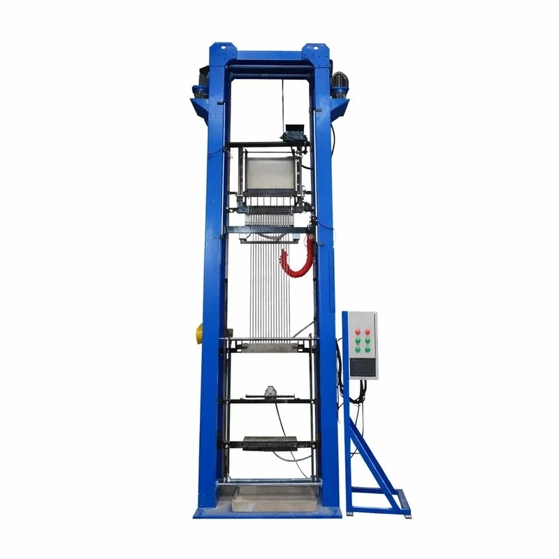
AGRP 800°C High-Temperature Cable
For those seeking a high-performance industrial cable that withstands the most intense heat, the AGRP 800°C is the superior choice. This fiberglass cable with a nickel-plated conductor is designed to overcome the challenges of industrial heating systems and high-temperature furnaces, offering exceptional durability and performance. Its ability to operate at 800°C makes it an essential component for industrial automation in extreme thermal environments. If your project requires a temperature-resistant cable that guarantees operational continuity and minimizes downtime, the AGRP 800°C is the robust and reliable solution you need for your high thermal demand installations.
The AGRP 800°C high-temperature cable represents the forefront of wiring solutions for extremely severe industrial environments, capable of withstanding continuous temperatures of up to 800°C. Its advanced design incorporates a braided nickel-plated copper conductor, which not only enhances resistance to oxidation and corrosion at high temperatures but also optimizes flexibility. The insulation, composed of a triple layer of fiberglass braid and mica tape, provides unparalleled thermal and electrical protection, ensuring signal integrity and operational safety under the most critical conditions. This cable for extreme heat applications is indispensable in industries where reliability is paramount, such as metallurgy or power generation.
The AGRP 800°C cable is ideal for a wide range of industrial applications demanding superior resistance to extreme temperatures:
-
Heat Treatment Furnaces and Foundries: Essential for the internal wiring of annealing furnaces, metal melting furnaces, and forging equipment, where temperatures exceed 500°C.
-
High-Power Heating Systems: Used in the connection of heater elements in industrial processes such as vulcanization, plastic extrusion, and glass manufacturing.
-
Petrochemical Industry and Refineries: Suitable for instrumentation and control wiring in high-temperature process areas, guaranteeing safety and reliability.
-
Power Generation: Applied in thermal power plants and cogeneration facilities for wiring equipment exposed to intense heat, such as turbines and boilers.
-
Ceramic and Cement Industries: Ideal for wiring rotary kilns and dryers in the production of construction materials, where thermal conditions are highly demanding.
|
Feature |
Advantage |
|---|---|
|
Braided Nickel-Plated Copper Conductor |
Provides excellent resistance to oxidation and corrosion at high temperatures, in addition to greater flexibility and durability. |
|
Reinforced Insulation (Fiberglass + Mica) |
The multi-layer construction offers superior thermal and electrical protection, allowing safe and stable operation up to 800°C. |
|
800°C Temperature Range |
Allows its use in the most extreme industrial applications, where other cables would fail, guaranteeing operational continuity. |
|
High Dielectric Strength |
With a test voltage of 2000V, it ensures excellent insulation capacity and minimizes the risk of electrical failures. |
|
Aging Resistance |
Its high-quality material composition gives it a long service life, reducing maintenance and replacement costs. |
|
Characteristic |
Detail |
|---|---|
|
Type |
AGRP |
|
Conductor |
Braided Nickel-Plated Copper Wire |
|
Insulation |
Fiberglass Braid + Mica Tape + Fiberglass Braid |
|
Temperature Range |
Up to 800°C |
|
Rated Voltage |
300V / 500V |
|
Test Voltage |
2000V |
|
Insulation Resistance |
≥1500 MΩ·km (at 20°C) |
|
OD Tolerance |
±0.1mm |
|
Additional Dimensions |
See dimensions table below for details by section. |
Dimensions and Electrical Properties Table (AGRP)
|
Section (mm²) |
Conductor Construction (No. x φmm) |
Insulation Thickness (mm) |
Outer Diameter (O.D.) (mm) |
Max. Resistance at 20°C (Ω/km) |
Packaging (m/roll) |
|---|---|---|---|---|---|
|
0.5 |
7 x 0.30 |
0.5 |
2.3 ± 0.3 |
40.8 |
100 |
|
0.75 |
11 x 0.30 |
0.5 |
2.5 ± 0.3 |
24.3 |
100 |
|
1.0 |
14 x 0.30 |
0.5 |
2.6 ± 0.3 |
20.0 |
100 |
|
1.5 |
21 x 0.30 |
0.5 |
2.9 ± 0.3 |
12.6 |
100 |
|
2.0 |
28 x 0.30 |
0.6 |
3.3 ± 0.5 |
9.84 |
100 |
|
2.5 |
35 x 0.30 |
0.6 |
3.6 ± 0.5 |
7.37 |
100 |
|
4.0 |
56 x 0.30 |
0.8 |
4.7 ± 0.5 |
4.83 |
100 |
|
6.0 |
84 x 0.30 |
0.8 |
5.5 ± 0.5 |
3.26 |
100 |
|
10.0 |
84 x 0.40 |
0.8 |
6.6 ± 0.5 |
1.80 |
100 |
|
16.0 |
228 x 0.30 / 126 x 0.40 |
0.8 |
7.8 ± 0.5 |
1.31 |
100 |
|
25.0 |
196 x 0.40 / 361 x 0.30 |
0.8 |
9.5 ± 0.5 |
0.758 |
100 |
|
35.0 |
394 x 0.30 |
1.0 |
11.2 ± 1.0 |
0.548 |
100 |
|
50.0 |
396 x 0.40 / 703 x 0.30 |
1.2 |
13.2 ± 1.0 |
0.384 |
100 |
|
Standard |
Q321281KLA02-2009 |
||||
|
Color |
White (other colors customizable) |
To facilitate the selection and highlight the advantages of the AGRP 800°C cable against other high-temperature options, we present the following comparison table:
|
Characteristic |
BGR Cable (500°C) |
AGRP Cable (800°C) |
GN 500 Cable (1000°C) |
|---|---|---|---|
|
Max Temperature |
500°C |
800°C |
1000°C |
|
Conductor |
Bare Copper |
Braided Nickel-Plated Copper |
Pure Nickel |
|
Primary Insulation |
Fiberglass + Mica |
Fiberglass + Mica |
Fiberglass + Mica |
|
Typical Applications |
Industrial ovens, heating systems, Oil & Gas |
Heat treatment furnaces, foundries, petrochemical |
Sintering furnaces, metallurgy, aerospace |
|
Key Advantage |
Balance between performance and cost for 500°C |
Higher oxidation resistance and flexibility for 800°C |
Extreme oxidation resistance and stability for 1000°C |
FAQ
How does ambient temperature affect the current-carrying capacity (ampacity) of the cable?
Ampacity is defined as the maximum current, in amperes, that a conductor can carry continuously under conditions of use without exceeding its temperature rating. Ambient temperature is a critical factor, as a cable's ability to dissipate heat generated by the Joule effect depends directly on the thermal difference between the conductor and the surrounding medium.
When the ambient temperature increases, the cooling capacity of the cable decreases. To avoid premature degradation of the insulation, correction factors (derating factors) must be applied. According to international regulations such as the NEC (National Electrical Code), the tabulated ampacity (generally calculated at 30°C or 40°C) must be multiplied by a factor less than 1.0 if the ambient temperature is higher.
|
Ambient Temperature (°C) |
Correction Factor (90°C Insulation) |
Real Capacity (Example 100A) |
|---|---|---|
|
30°C |
1.00 |
100 A |
|
40°C |
0.91 |
91 A |
|
50°C |
0.82 |
82 A |
|
60°C |
0.71 |
71 A |


