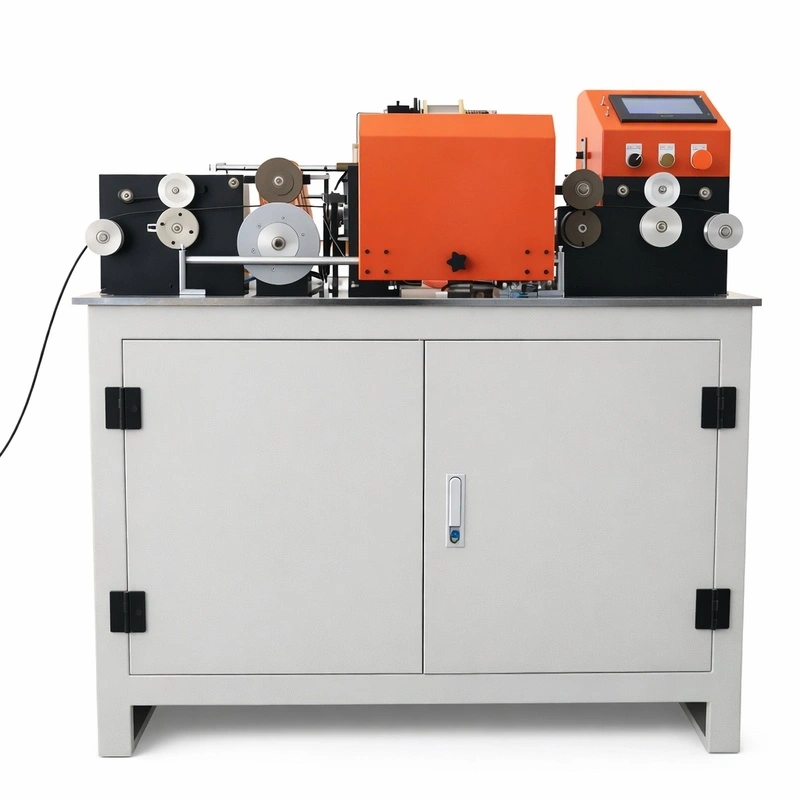
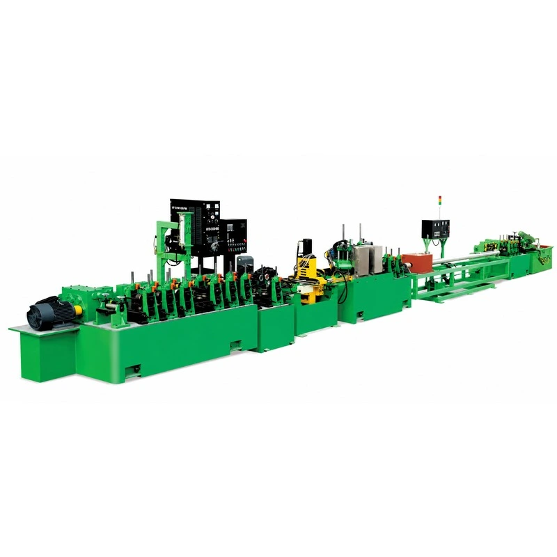
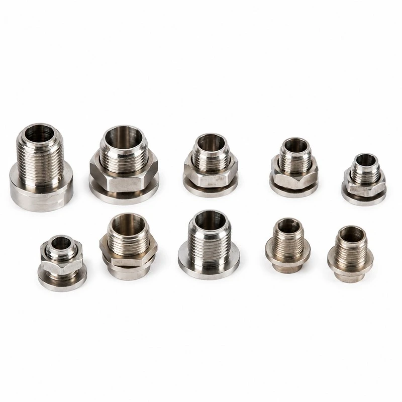
What are Tube Drawing Machines and How Do They Work?
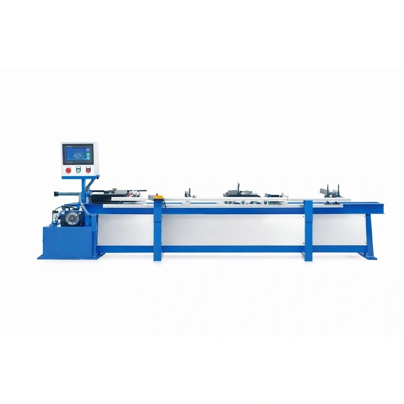
Industrial tube drawing machines —colloquially classified in metalworking as draw benches or tube drawing machines— are high-tonnage mechanical or hydraulic systems engineered for the cold forming of hollow profiles. Their primary objective is to simultaneously reduce the outer diameter (OD), decrease the wall thickness (WT), and substantially enhance the mechanical properties (such as yield strength and tensile hardness) through strain hardening (work hardening).
The process utilizes plastic deformation driven by linear tension. Prior to drawing, one end of the raw tube (mother tube) undergoes a swaging or pointing process to reduce its diameter locally. This pointed end is inserted through a high-rigidity tungsten carbide or industrial diamond die. Heavy-duty pneumatic or hydraulic gripping jaws mounted on a drawing carriage clamp the point, and a massive tractive force (ranging from 5 to over 150 metric tons) pulls the tube through the toolset. To secure absolute control over the internal diameter and achieve high-precision inner surface finishes, a mandrel (either fixed or floating) is positioned coaxially inside the deformation zone.
Types of Tube Drawing Machines and Draw Benches
- Chain-Driven Draw Benches: The undisputed workhorses of heavy metallurgy. They rely on high-torque electric motors coupled with heavy-duty roller chain drives. These systems are highly cost-effective and perfectly suited for processing long, straight structural tubing (up to 24 meters or more) requiring massive pulling forces in carbon and stainless steels.
- Hydraulic Draw Benches: Advanced-tier machinery that replaces traditional chain mechanisms with high-pressure, precision hydraulic cylinders. They provide infinitely variable drawing speeds, zero mechanical vibration, and perfectly smooth force delivery. This makes them mandatory for processing high-value, sensitive alloys (titanium, zirconium, nickel-based superalloys) used in aerospace and nuclear applications.
- Rotary Bull Blocks (Continuous Drawing Systems): Instead of a linear bed, the tubing is drawn and simultaneously wound onto a large-diameter rotating drum. This methodology is restricted to thin-walled, small-diameter tubes with enough elasticity to bend without collapsing, representing the absolute manufacturing standard for the copper and aluminum tubing industries (HVAC, refrigeration, and fluid transport lines).
Engineering Fundamentals: Drawing Force Calculation
To accurately size a drawing machine frame and motor power, Heatecx engineers calculate the theoretical pulling force (F). This mathematical model integrates the material’s mean flow stress and tool friction:
Drawing Force (F) = A1 * σm * ln(A0 / A1) * (1 + μ * cot α)
Where:
- A0 and A1 represent the cross-sectional areas of the tube before and after processing.
- σm (Mean Sigma) is the mean flow stress of the metal matrix during deformation.
- ln is the natural logarithm of the area reduction ratio.
- μ (Mu) is the friction coefficient at the die-tube contact interface.
- cot α (Cotangent of Alpha) represents the semi-die angle of the approach zone.
Technical Selection Guide for Tube Drawing Equipment
Specifying an industrial draw bench requires precise metallurgical calculations. When engineering your next asset, consider these essential variables:
- Material Metallurgy and Deformation Resistance: The required pulling force is directly proportional to the material's yield strength and the cross-sectional area reduction. Duplex stainless steels or exotic alloys require up to three times the drawing tonnage compared to copper or aluminum for identical geometric reductions.
- Dimensional Range and Structural Tolerances: Map out your maximum and minimum inlet and outlet dimensions (OD, ID, and WT). This data dictates the physical length of the bench bed, the maximum carriage stroke, and the required structural stiffness of the mandrel retention back-stand.
- Throughput Configuration (Single-Strand vs. Multi-Strand): For high-volume manufacturing plants, double, triple, or quadruple drawing configurations allow the simultaneous processing of multiple tubes within a single draw cycle, drastically lowering energy consumption per ton produced.
- Automation Level & Material Handling Systems: Evaluate the integration of automatic overhead tube loaders, indexable material charging tables, pneumatic discharge arms to prevent surface scratching, and automated inline flying or fixed saws.
Process Optimization: Troubleshooting Drawing Defects
Heatecx draw benches feature advanced controls designed to eradicate common process defects:
- Scoring and Longitudinal Scratches: Often caused by lubricant breakdown or particulate buildup within the die throat. Our systems feature continuous high-pressure oil micro-filtration to eliminate suspended solids.
- Point Breakage: Occurs due to incorrect pointing geometry or excessive jerk forces at draw initiation. Heatecx benches utilize software-driven S-curve acceleration profiles to eliminate sudden mechanical stress peaks.
- Eccentricity and Wall Thickness Variation: Caused by misalignment between the internal mandrel rod and the die center. We design ultra-rigid, self-centering back-stands to guarantee absolute coaxial alignment.
How Heatecx Can Help You
At Heatecx, we bridge the gap between heavy machinery engineering and thermal/process optimization to deliver turnkey tube drawing lines. We do not supply off-the-shelf equipment; we design and manufacture custom-engineered draw benches tailored to your exact floor layout and production challenges. From finite element analysis (FEA) of the machine frame to integrated forced-lubrication loops and optimized tooling geometry, Heatecx guarantees maximum asset uptime, low operational costs, and compliance with global safety regulations.