Ceramic Infrared Heaters
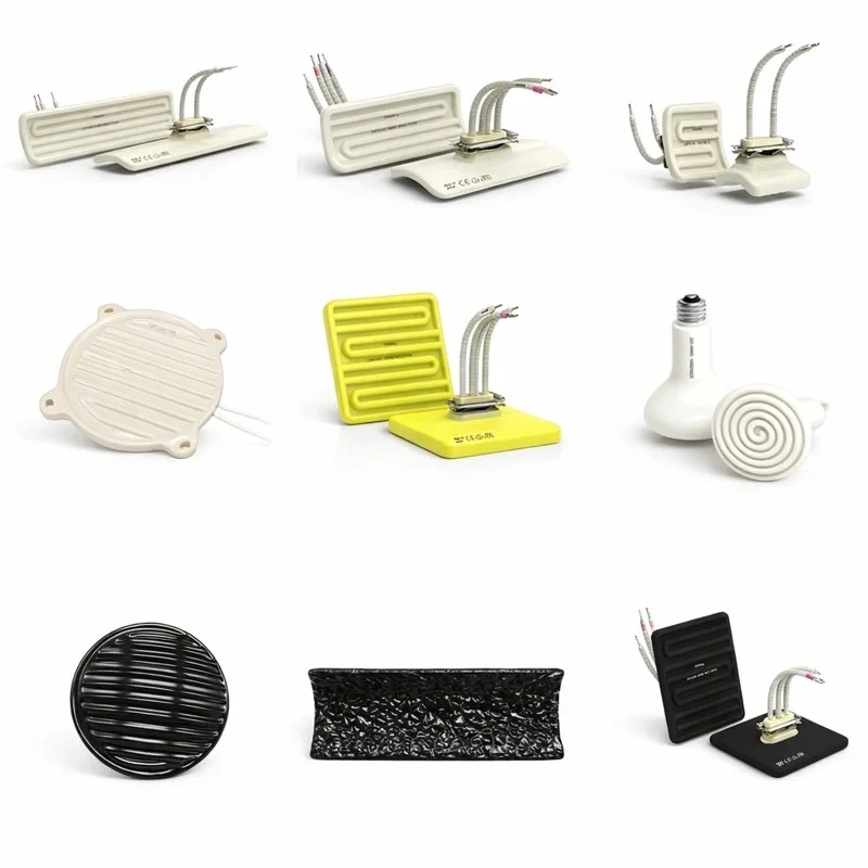
Ceramic infrared heaters are industrial heating elements that generate radiant heat through a nickel-chromium resistance wire embedded inside a cast ceramic body. Unlike convection-based heating systems, these emitters transfer energy directly to the target material through electromagnetic radiation in the medium and long infrared range, without needing to heat the surrounding air first. This characteristic makes them the reference solution for industrial drying, curing, thermoforming, and preheating processes where energy efficiency and thermal uniformity are decisive factors.
The operating principle relies on matching the wavelength emitted by the heater to the peak absorption band of the material being processed. Most organic materials, paints, plastics, and food products show peak absorption between 3 and 7 microns — a range that corresponds precisely to the characteristic emission of a ceramic infrared heater operating between 300°C and 800°C surface temperature. This physical correspondence explains why ceramic infrared technology has remained an industrial standard for decades, in many cases outperforming short-wave alternatives whenever the goal is deep, uniform heating rather than instantaneous thermal response.
Construction and operating principle
A ceramic infrared heater is built from three main structural elements:
- Embedded NiCr resistance wire: a nickel-chromium alloy wire or ribbon (typically NiCr 80/20) housed inside the ceramic body through a casting molding process. Encapsulation shields the resistance wire from direct contact with the process environment, extending its service life against oxidation and mechanical shock.
- Ceramic body: manufactured from high-purity refractory ceramics (steatite or similar magnesium-silicate-based compositions), chosen for dimensional stability at high temperature, low lateral thermal conductivity, and dielectric properties that guarantee electrical insulation between the resistance wire and the outside.
- Vitrified glaze surface finish: a glass-like coating applied and fired onto the ceramic body surface. Besides improving the emitter's emissivity, it acts as a barrier against moisture, chemical corrosion, and mechanical wear in aggressive industrial environments.
When electrical current is applied, the internal resistance raises the ceramic body's temperature, which in turn radiates energy as infrared heat toward the target material. The ceramic mass acts as a thermal buffer, delivering a more stable emission with fewer output spikes than other radiant technologies, at the cost of a slower response time compared with short-wave quartz lamps.
Physical fundamentals of infrared radiation applied to industrial heating
Understanding the electromagnetic spectrum is key to correctly sizing an infrared heating installation. Infrared used in industrial processes is conventionally divided into three bands:
|
Band
|
Approximate wavelength
|
Associated emitter temperature
|
Behavior
|
|
Short infrared (NIR)
|
0.78 – 1.4 microns
|
> 1800°C (halogen quartz lamps)
|
Low surface penetration, near-instant response
|
|
Medium infrared (MIR)
|
1.4 – 3 microns
|
800 – 1800°C
|
Medium penetration, suitable for moderate-cycle processes
|
|
Long / far infrared (FIR)
|
3 – 10 microns
|
300 – 800°C (ceramic heaters)
|
Deep, uniform penetration, gradual heating
|
The relationship between an emitting body's temperature and the wavelength at which it radiates most intensely is described by Wien's displacement law. At the typical surface temperatures of a ceramic heater (300–800°C), the emission peak falls precisely in the 3 to 7 micron band, matching the peak absorption band of most polymers, resins, water- and solvent-based paints, textile fibers, and moisture-containing food products. This spectral match — not electrical power alone — is what determines the real thermal transfer efficiency of an infrared system, which is why selecting the right heater requires knowing the material's absorption spectrum before its rated power.
Another relevant parameter is the emissivity of the radiating surface. The vitrified glaze coating the ceramic body raises surface emissivity to values near 0.85–0.95 (versus the theoretical maximum of 1.0 for a perfect black body), translating into highly efficient radiant energy transfer compared with polished metal surfaces, whose emissivity can fall below 0.3.
Types and construction variants
|
Variant
|
Characteristics
|
Typical application
|
|
Flat emitter
|
Solid ceramic body with a flat radiating surface; uniform emission across the entire front face
|
Drying and curing of flat surfaces, tunnel ovens
|
|
Curved emitter
|
Curved design that maximizes the distance between the resistance wire and the mounting surface, reducing temperature at the wiring area
|
Installations where adjacent wiring requires extra thermal protection
|
|
Vacuum / hollow emitter
|
Hollow ceramic body filled with high-density insulating material; reduces heat loss toward the back
|
Processes requiring maximum energy efficiency and shorter preheating times
|
|
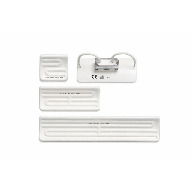
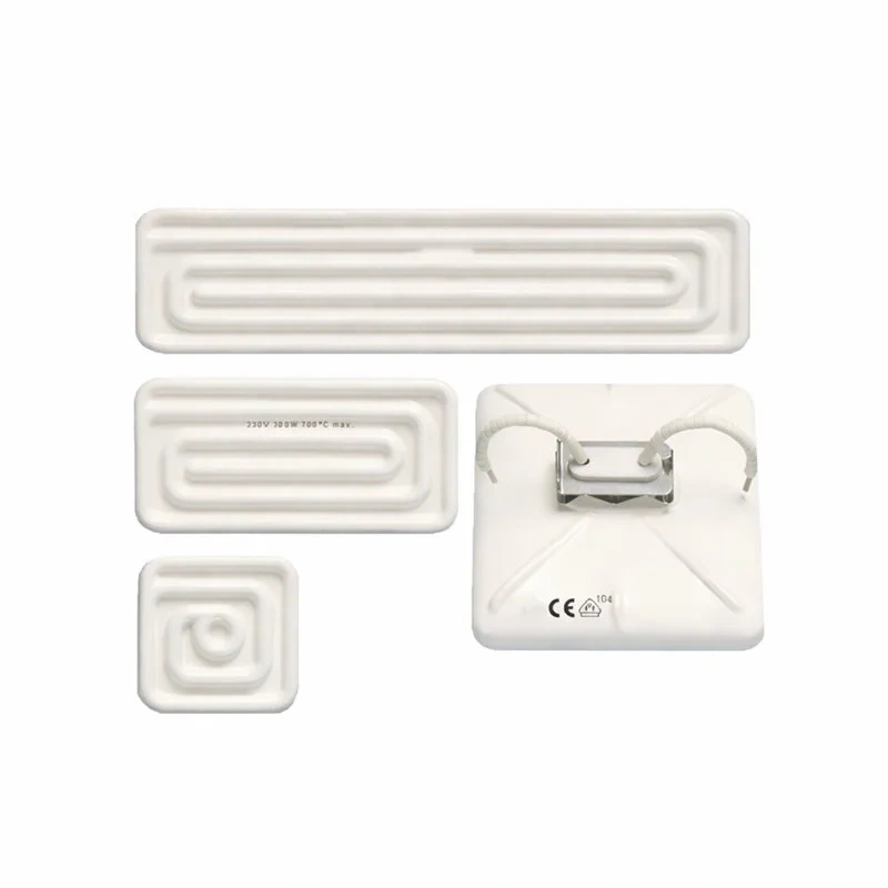
Full, half and quarter formats
|
Standard subdivisions of the ceramic panel to match the radiating surface to the oven or line geometry
|
Modular panel configuration in custom installations
|
|
Low-voltage emitter (24V / 48V)
|
Reduced supply for environments with electrical safety restrictions or integration with low-power control systems
|
Compact machinery, laboratory applications, or lines with adjacent ATEX requirements
|
|
Emitter with integrated reflector
|
Incorporates a polished metal reflective housing at the rear to redirect radiation toward the target
|
Installations requiring the beam concentrated on a small area with minimal side losses
|
Electrical wiring configurations
Ceramic infrared heaters can be grouped into banks or arrays to cover larger surfaces. The most common electrical configurations are:
- Parallel connection: each heater receives the full line voltage; this is the most common configuration because it allows a failed element to be isolated and replaced without affecting the rest of the array.
- Series connection: several heaters share the line current, reducing the voltage applied to each; used when total power needs to be reduced without additional controllers, though a single element failure interrupts the whole circuit.
- Zone control: the array is divided into independent groups governed by solid-state relays (SCR) or contactors, allowing differentiated power profiles across the width or length of the production line to compensate for edge losses or material thickness variation.
Reference technical specifications
|
Parameter
|
Typical range
|
|
Power
|
125W – 1000W per element (modular configurations for higher power)
|
|
Rated voltage
|
230V (other voltages available on request)
|
|
Maximum surface temperature
|
Up to 800°C
|
|
Emission range
|
Medium wave and long wave (far infrared)
|
|
Peak emission wavelength
|
Approximately 3 – 7 microns
|
|
Recommended radiation distance
|
100 – 200 mm between emitter and target material
|
|
Common standard dimensions
|
122 × 60 mm; 245 × 60 mm; 245 × 122 mm; 245 × 245 mm (full/half/quarter formats)
|
|
Nominal service life under proper conditions
|
Several tens of thousands of accumulated operating hours
|
|
Control option
|
Integrated type J or type K thermocouple for precise temperature monitoring and control
|
|
Electrical connection
|
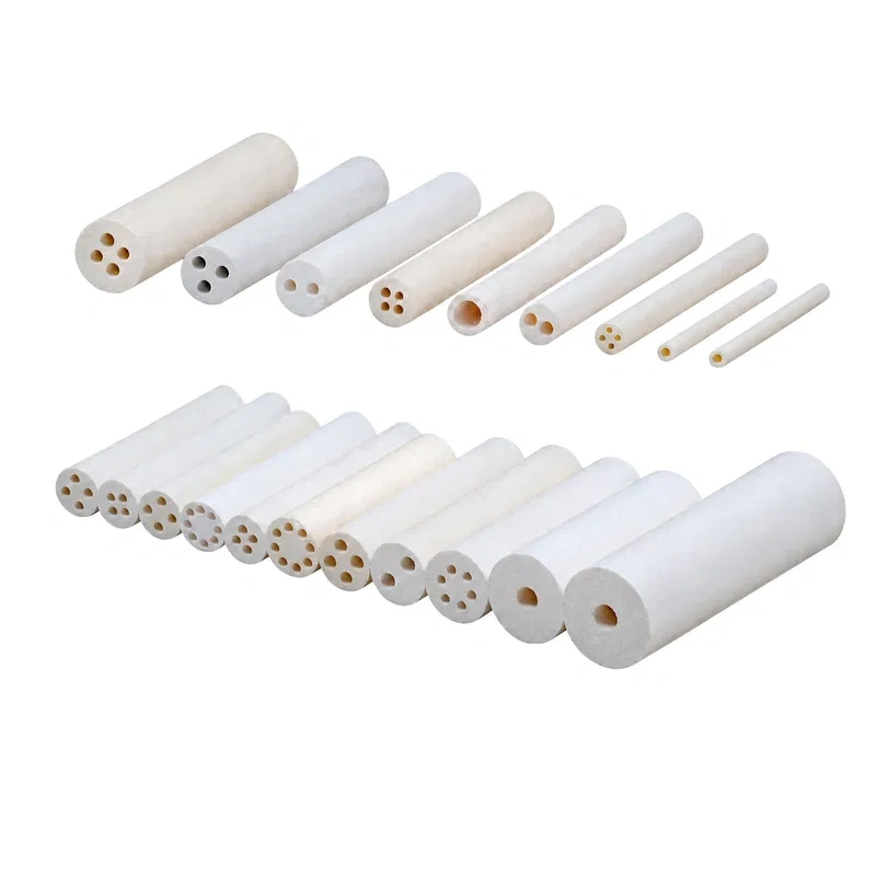
Terminals protected by ceramic insulating beads, typical lead length 100 mm
|
Power density and thermal sizing
Correctly sizing a ceramic infrared heater installation depends not only on the element's rated power, but on the power density applied per unit surface of the material being heated, typically expressed in W/cm². As a rough reference for preliminary sizing:
|
Process type
|
Indicative power density
|
Notes
|
|
Light surface drying (inks, water-based varnishes)
|
0.5 – 1.5 W/cm²
|
Long cycles, low overheating risk
|
|
Paint and coating curing
|
1.5 – 3 W/cm²
|
Requires temperature control to avoid premature surface skinning
|
|
Plastic sheet thermoforming
|
2 – 4 W/cm²
|
Depends on thickness and polymer type; PVC, PET and ABS have different absorption behaviors
|
|
Preheating of metal or ceramic parts
|
3 – 6 W/cm²
|
High thermal mass, requires longer exposure or higher density
|
The approximate calculation of total power required starts from the surface area to be heated, the target temperature rise, the material's specific heat, and the available cycle time. In practice, it is recommended to oversize the array by 15% to 25% relative to the theoretical calculation to compensate for lateral convection losses, reflection, and material variability, then fine-tune via zone control or power modulation (phase-angle or zero-cross SCR control).
Materials used and their function
|
Component
|
Material
|
Function
|
|
Internal resistance
|
NiCr 80/20 alloy (or other Ni-Cr alloys depending on power requirements)
|
Joule-effect heat generation; stable resistivity at high temperature
|
|
Ceramic body
|
Steatite / magnesium silicate refractory ceramic
|
Electrical insulation, structural support, infrared emission
|
|
Surface coating
|
Vitrified glaze
|
Corrosion protection, improved emissivity, wear resistance
|
|
Internal filler (hollow variant)
|
High-density insulating material
|
Reduction of rear heat losses
|
|
Terminals
|
Ceramic insulating beads
|
Electrical insulation of connections against temperature and moisture
|
|
Optional sensor
|
Type J or K thermocouple
|
Temperature feedback for process control
|
Selection criteria
|
Criterion
|
Technical consideration
|
|
Required wavelength
|
Verify the target material's peak absorption (typically 3–7 microns) against the emitter's emission band
|
|
Power density (W/cm²)
|
Determine based on available process time and thermal mass of the material being heated
|
|
Emitter-to-material distance
|
Adjust within the 100–200 mm range to optimize radiant transfer without localized overheating
|
|
Construction geometry
|
Flat for uniform surfaces; curved when sensitive wiring is close to the mounting point; hollow/vacuum when energy efficiency is the priority
|
|
Process control needs
|
Specify integrated type J or K thermocouple if the process requires closed-loop temperature monitoring
|
|
Panel format
|
Full, half or quarter, according to the modular configuration required by the oven or production line
|
|
Installation environment
|
Assess exposure to moisture, corrosive vapors, or vibration to confirm suitability of the vitrified glaze and mounting system
|
Applications by industry
|
Industry
|
Typical process
|
Benefit of ceramic infrared heating
|
|
Plastics and packaging
|
Sheet thermoforming, bottle preform heating, plastic part welding
|
Deep, uniform heating without degrading the polymer surface
|
|
Paint and coatings
|
Liquid and powder paint curing, varnish and primer drying
|
Reduced curing time and lower energy consumption vs. convection ovens
|
|
Textile
|
Drying fabrics after dyeing, dye fixation, fiber preconditioning
|
Uniform distribution across variable fabric widths via modular arrays
|
|
Food
|
Industrial baking, fruit and vegetable dehydration, temperature holding in cooking lines
|
Contactless heating, compatible with hygiene and dry-cleaning requirements
|
|
Paper and cardboard
|
Print ink drying, drying after coating and lamination processes
|
High line speed thanks to radiant transfer efficiency
|
|
Automotive
|
Adhesive and sealant curing, part preheating before assembly, LED headlight defrosting
|
Localized, low-voltage heating for specific applications
|
|
Wood
|
Varnish and lacquer drying, preheating before panel pressing
|
Deep penetration suited to porous surfaces
|
|
Ceramics and glass
|
Preheating before decoration processes, glaze drying
|
The emitter itself withstands high ambient-temperature environments
|
Ceramic infrared heaters vs. other heating technologies
|
Technology
|
Response time
|
Heat distribution
|
Typical service life
|
Best use
|
|
Ceramic infrared heater
|
Slow (tens of seconds)
|
Uniform, deep heat
|
Very long
|
Drying, curing and thermoforming with continuous cycles
|
|
Short-wave quartz lamp
|
Very fast (under 1 s)
|
Concentrated, surface heat
|
Medium (depends on on/off cycles)
|
Intermittent processes with frequent start/stop
|
|
SiC (silicon carbide) resistance
|
Fast
|
High temperature, intense radiation
|
Long
|
High-temperature furnaces (>1000°C)
|
|
Metal tubular resistance
|
Medium
|
Combined convection + radiation
|
Medium
|
Air heating and enclosed environments
|
Advantages and limitations
Main advantages
- Considerably longer service life than short-wave quartz lamps in continuous-cycle applications, thanks to the ceramic body's mechanical and chemical protection.
- Uniform heat distribution across the entire emitter surface, without the localized hot spots that quartz filaments can present.
- High energy efficiency (over 85% in properly sized installations), by concentrating radiation in the peak absorption band of most industrial materials.
- Robustness against vibration, moisture, and chemically aggressive environments thanks to the vitrified glaze.
- Interchangeability and ease of maintenance: damaged elements are replaced individually without stopping the entire line if the array is properly zoned.
Limitations to consider
- Slow thermal response time (tens of seconds) compared with short-wave quartz lamps, making them less suited to very frequent start-stop processes.
- Greater mass and thermal inertia, requiring longer cooling times before handling or transporting heaters after use.
- Sensitivity of the ceramic body to direct mechanical impact and extreme thermal shock, requiring more careful handling than metal tubular resistances.
Common failure modes and preventive maintenance
- Ceramic body cracking: caused by sudden thermal shock or mechanical impact; prevented by avoiding excessively fast heating ramps and protecting the heater during handling.
- Vitrified glaze degradation: prolonged exposure to acidic vapors or mechanical abrasion reduces surface emissivity and accelerates corrosion of the base ceramic; periodic visual inspection is recommended.
- Failure of the embedded internal resistance wire: usually caused by overvoltage, extreme thermal cycling, or the natural end of the NiCr wire's service life; not repairable, requires replacement of the complete element.
- Integrated thermocouple failure: results in drift or loss of signal; periodic verification of sensor continuity and calibration is recommended as part of the control system's maintenance schedule.
- Buildup of process residue or dirt: reduces emission efficiency; dry cleaning with the heaters disconnected and cold is recommended, avoiding thermal shock from contact with liquids.
Storage, handling, and installation
- Storage: keep heaters in their original packaging, in dry environments with controlled relative humidity; moisture absorbed by the ceramic body before first startup can cause microcracking from sudden vaporization when reaching operating temperature.
- First startup: an initial curing cycle with gradual power ramp-up (slow ramp to nominal operating regime) is recommended to expel residual moisture from the ceramic body before exposing it to maximum temperature.
- Handling: avoid impact or drops of the heater, especially in flat and curved formats, whose ceramic body is more sensitive to fracture from point impact than from distributed load.
- Mechanical mounting: use the brackets and clamps specified by the manufacturer, avoiding excessive tightening that could generate localized mechanical stress on the ceramic body.
- Safety distance: maintain sufficient separation between the heater and flammable or heat-sensitive materials not intended for the process, in accordance with the recommended radiation distance and applicable fire safety regulations.
- Pre-use inspection: visually verify the integrity of the vitrified glaze and the absence of cracks before each startup, especially after extended storage or transport periods.
Manufacturing process
- Resistance alloy preparation: selection and forming of the NiCr wire or ribbon according to target power and electrical resistance.
- Ceramic powder pressing and compaction: preparation of the base ceramic mix through cold pressing or isostatic compaction, prior to final body molding.
- Ceramic body molding: casting of the ceramic body (flat, curved, or hollow), encapsulating the resistance wire in its final position.
- Curing and sintering: high-temperature firing in a controlled kiln to consolidate the ceramic structure and fix the embedded resistance wire.
- Vitrified glaze application: surface coating and final firing to develop the protective glass layer.
- Terminal assembly: installation of ceramic insulating beads and electrical connections, with or without an integrated thermocouple.
- Electrical and dimensional testing: verification of electrical resistance, dielectric strength, and dimensional conformity for each unit.
- Functional test at rated power: controlled heating cycle to verify the temperature curve and detect hidden defects in the embedded resistance.
- Final quality control: visual inspection of the glaze, dimensional verification, and packaging for dispatch.
Application case
A plastic sheet thermoforming line for packaging needs to raise sheet temperature uniformly before molding, avoiding hot spots that cause uncontrolled deformation. Installing a modular array of flat ceramic infrared heaters, arranged in full and half-panel formats across the sheet width, achieves uniform thermal distribution at a radiation distance of 150 mm. Adding type K thermocouples to the central elements of the array enables closed-loop temperature control, reducing rejects from defective thermoforming and improving energy consumption compared with forced convection systems.
A second common scenario arises in powder coating curing on metal parts with irregular geometry. Here, an array of curved emitters, oriented to partially wrap the part, reaches areas that a flat panel would leave in thermal shadow. Combining vacuum/hollow emitters in higher-exposure sections with standard flat emitters in easily accessible zones balances the curing tunnel's overall energy consumption, while SCR-based zone control adjusts each group's power based on the metal mass present at each section of the line.
Why choose Heatecx
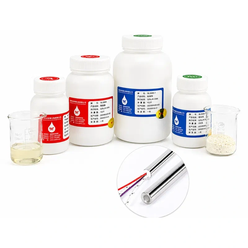
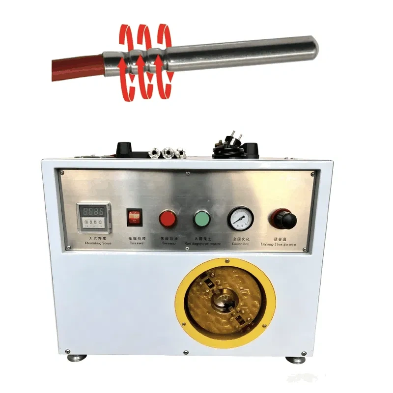
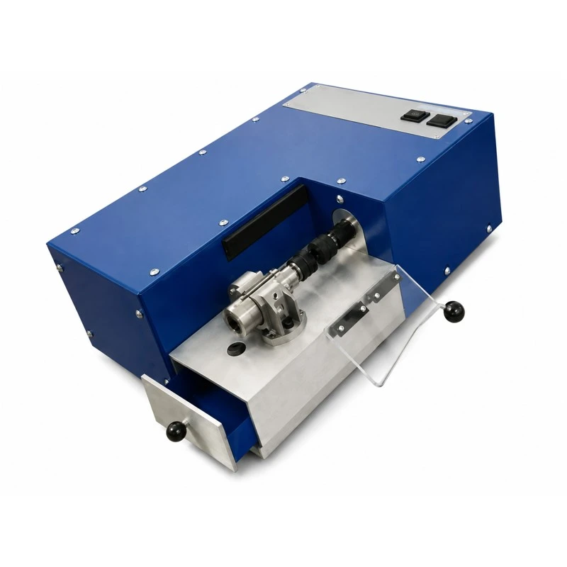
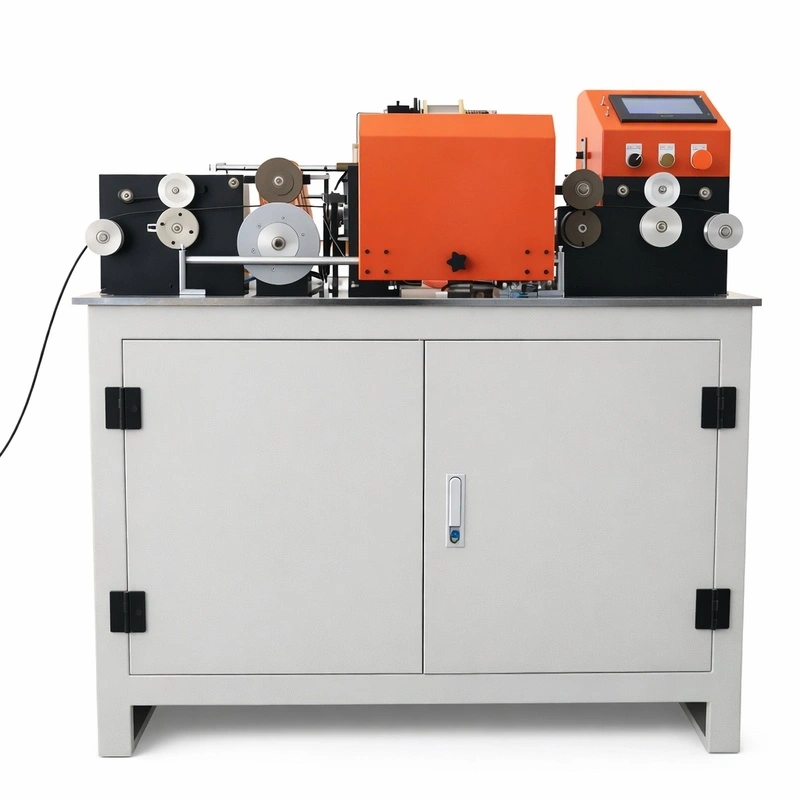
Heatecx is a direct manufacturer of ceramic infrared heaters as well as the machinery and raw materials used to produce them, allowing full control over the quality of every element — from the resistance alloy to the final vitrified glaze. The vertical integration of our Shenzhen facility, spanning ceramic molding through terminal assembly, allows us to offer competitive lead times and customization capability in power, format, and integrated sensor type. Every production batch undergoes electrical continuity testing and 100% dimensional verification, and our technical support team assists in selecting the right heater based on material, process geometry, and thermal control requirements for each customer.
Related products