Ceramic Pad Heaters: Technical Datasheet
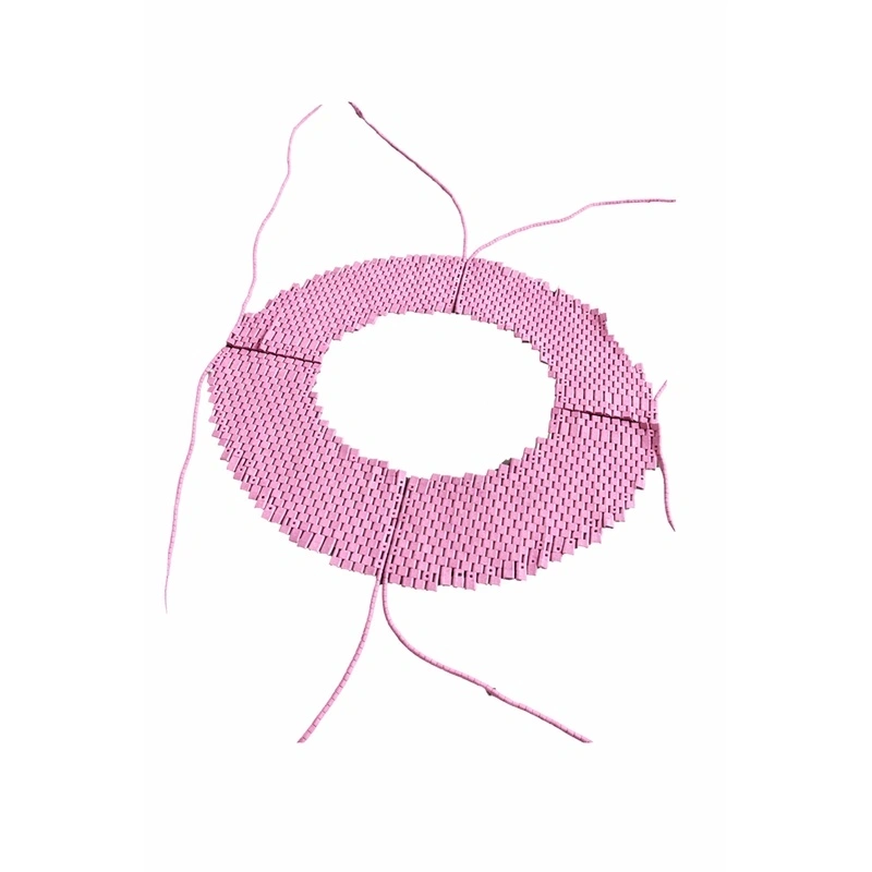
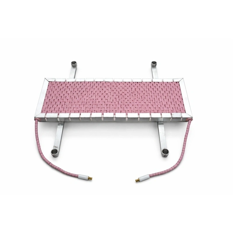
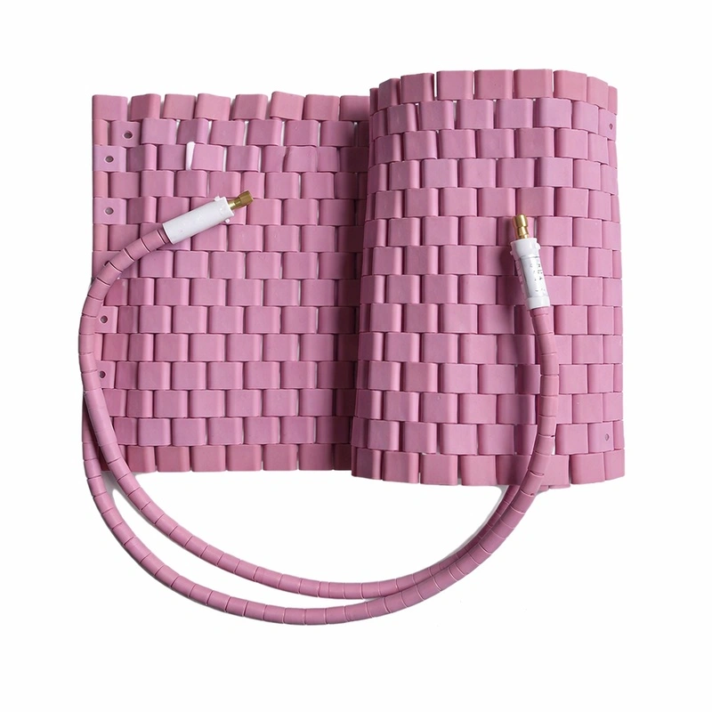
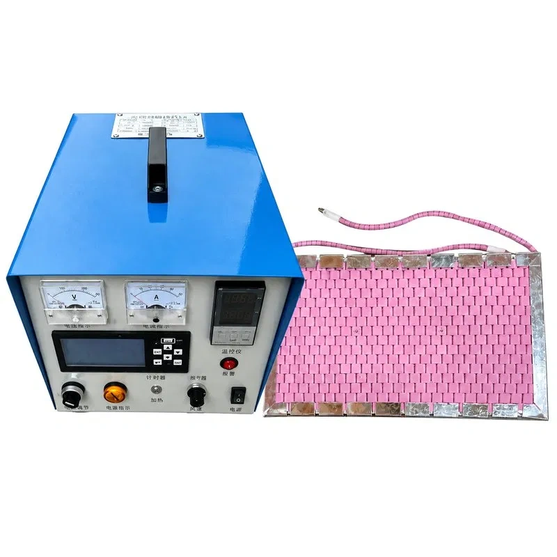
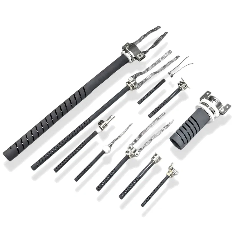
Ceramic pad heaters — also referred to in technical literature as flexible ceramic heating elements or caterpillar heaters — are electrical resistance heaters built from a nickel-chromium (NiCr) alloy heating wire threaded through a series of high-purity alumina ceramic beads or tiles, articulated together in a caterpillar-type configuration. This segmented, bead-by-bead construction is what gives ceramic pad heaters their ability to bend and conform to curved, irregular, or geometrically complex surfaces — a level of adaptability that a rigid ceramic heater simply cannot offer. Together with Silicon Carbide (SiC) heating elements, ceramic pad heaters are one of the core families within Heatecx's range of industrial heating elements, though their natural field of application is portable, local heat treatment rather than fixed furnace heating.
Inside this product family, several construction variants — rope-type, pad-type, split-type, angle-type, and custom-built — share the same working principle while differing in how they wrap around the workpiece. That format diversity is precisely what has made ceramic pad heaters the de facto standard for weld preheating and Post Weld Heat Treatment (PWHT) across the petrochemical, power generation, and pipeline construction industries worldwide.
Construction and material composition
The performance of a ceramic pad heater depends on three core components:
- Heating core: resistive wire made from a NiCr alloy (typically NiCr 80/20 or NiCr 70/30), chosen for its high electrical resistivity, oxidation resistance at elevated temperatures, and dimensional stability under repeated thermal cycling.
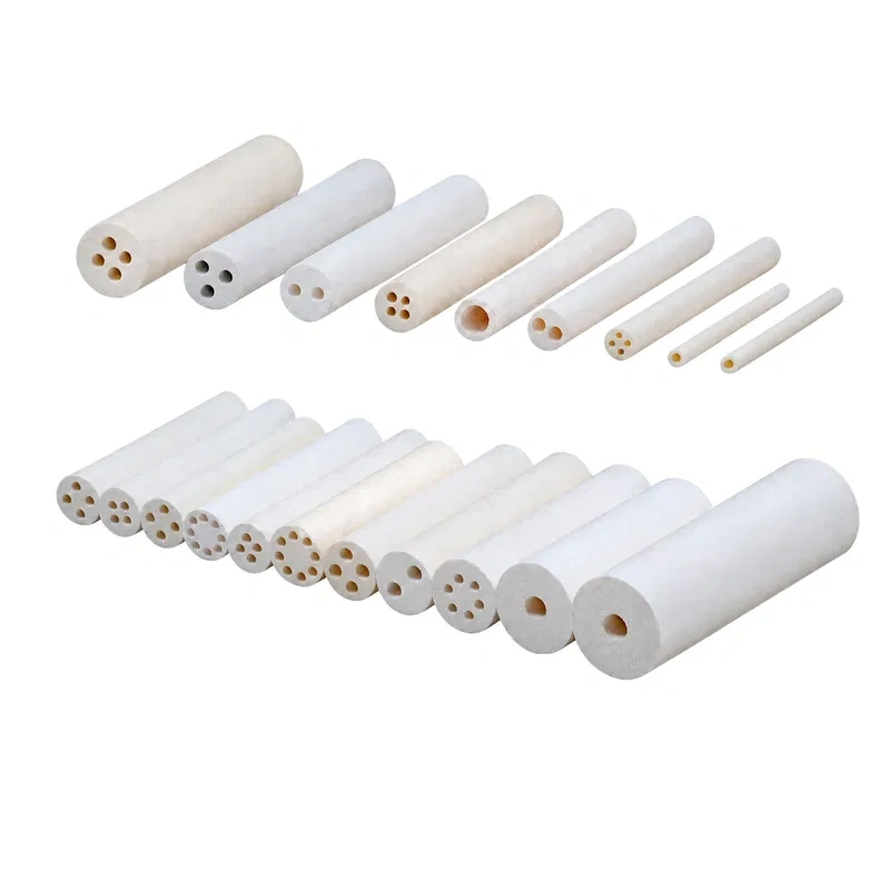
- Ceramic insulation: high-purity aluminum oxide (alumina, Al₂O₃) beads, tiles, or segments that surround the wire and function simultaneously as electrical insulation and as a thermal conductor toward the surface being heated.
- Outer sheath or mesh: a high-temperature fiberglass braid or flexible metallic mesh that binds the ceramic segments together, enables the caterpillar-style rolling motion, and protects the core from impact and abrasion during installation and use.
- Terminals and lead wires: high-temperature ceramic terminal blocks with fiberglass- or high-temperature silicone-insulated power leads, sized according to the working amperage of the heater.
This bead-by-bead modular design is what structurally sets ceramic pad heaters apart from other contact-heating technologies, such as silicone rubber heating blankets or mica band heaters, which use a continuous laminated heating element instead of articulated segments.
General technical specifications
|
Parameter
|
Typical value
|
|
Operating temperature range
|
0°C to 1050°C – 1300°C (design and variant dependent)
|
|
Heating core material
|
NiCr alloy (80/20 or 70/30)
|
|
Insulation material
|
High-purity alumina ceramic (Al₂O₃)
|
|
Surface power density
|
Configurable by design, typically 1–3 W/cm²
|
|
Supply voltage
|
110V, 220V, 380V or custom per project specification
|
|
Flexibility
|
360° caterpillar-style wrap, adaptable to elbows and reducers
|
|
Service life
|
Dependent on thermal cycling, surface contact quality, and operating conditions
|
|
Installation method
|
Direct wrap around the workpiece, secured with external mechanical fastening
|
Exact voltage, wattage, and dimensions are determined by the pipe or component diameter, target temperature, required heat-up time, and the power source available on site — which is why every ceramic pad heater order is effectively a custom engineering exercise rather than an off-the-shelf purchase.
Variants within the ceramic pad heater family
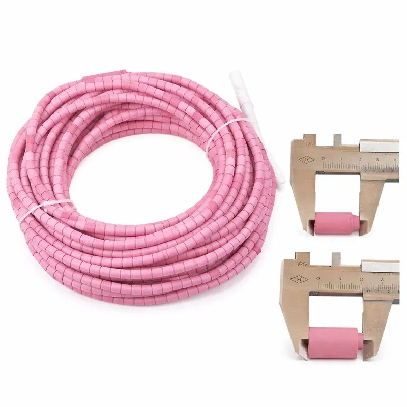
- Flexible Ceramic Rope Heaters (SCD): round cross-section format derived from caterpillar-heater technology, built to wrap directly around circumferential welds, elbows, tees, and components with complex geometry or in confined spaces where a flat heater cannot be installed.
- LH-LCD Ceramic Pad Heaters: the archetypal blanket- or pad-style format aimed at larger, more regular surfaces, providing uniform surface contact that supports even heating over a wider treatment area — this is the variant most commonly meant when buyers search for "ceramic pad heaters."
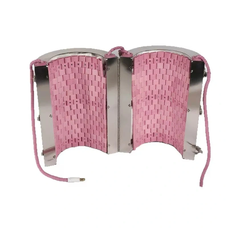
- Custom-built ceramic pad heater (fan-type / cylindrical): engineered for projects where standard sizing isn't viable, with voltage and power calculated in direct proportion to the size and mass of the workpiece.
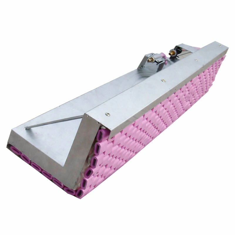
- Right-angle ceramic pad heater: a configuration purpose-built for local preheating and heat treatment of right-angle welds on steel structures.
- Split-type ceramic pad heater: also known as a split heater, this design simplifies installation and removal on small- and medium-diameter pipes that are already in place or in restricted-access locations.
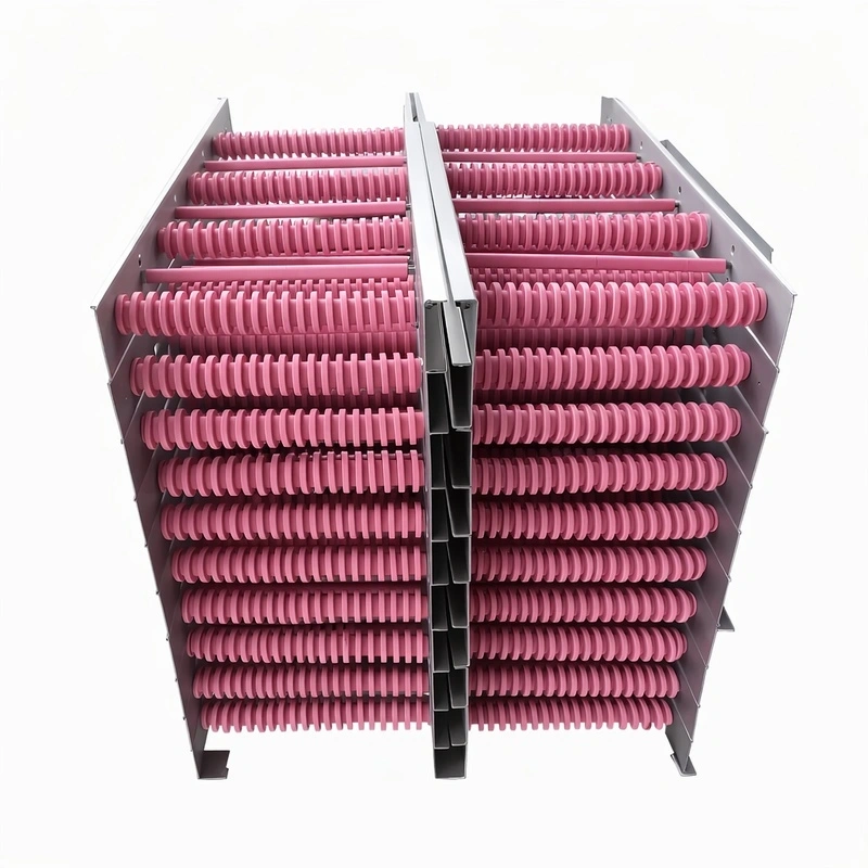
- Internal-frame ceramic pad heater: uses a 0Cr25Al5 (Fe-Cr-Al) heating alloy and is built for internal heating of metal structures and pressure vessels where high power density is required within a confined space.
Key industrial applications
- Weld preheating and PWHT (Post Weld Heat Treatment): the reference application for ceramic pad heaters, used in the fabrication and repair of piping, pressure vessels, and welded steel structures.
- Petrochemical and power generation industries: field heat treatment of welded joints in process plants, refineries, and power stations, where portability is as critical as thermal performance.
- Pipeline construction and maintenance: localized heating of welded pipe joints, frequently performed outdoors under restricted-access conditions.
- Metallurgy and heat treatment of components: localized annealing, normalizing, and tempering of irregularly shaped metal parts.
- Aerospace and automotive manufacturing: specialized component fabrication processes where standard heating solutions cannot conform to the part geometry.
- Foundry and precision metallurgy: controlled heating of molds and tooling with non-flat surfaces.
Ceramic pad heaters vs. other contact-heating technologies
|
Technology
|
Approx. max. temperature
|
Flexibility / geometry adaptation
|
Typical use
|
|
Ceramic pad heater (NiCr + alumina)
|
1050°C – 1300°C
|
High, full 360° caterpillar wrap
|
PWHT, weld preheating, field heat treatment
|
|
Silicone rubber heating blanket
|
Up to ~250°C – 300°C
|
Very high, continuous laminate
|
Low-temperature preheating, resin curing
|
|
Mica band heater
|
Up to ~450°C – 500°C
|
Moderate, semi-rigid
|
Extrusion and injection molding barrels
|
|
Rigid ceramic band heater
|
Up to ~750°C – 950°C
|
Low, fixed format
|
Extruder barrels, nozzles
|
|
SiC heating element
|
Up to 1500°C – 1600°C
|
None, rigid element
|
Fixed industrial electric furnaces
|
The key differentiator of the ceramic pad heater over mica bands or rigid ceramic heaters is its ability to operate at significantly higher temperatures without losing the ability to conform to irregular geometry — a combination no other contact-heating technology matches within the same thermal range.
Technical selection criteria
|
Decision factor
|
Technical consideration
|
|
Workpiece geometry
|
Straight pipe runs and circumferential welds point toward the rope-type format (SCD); large, regular surfaces favor the pad-type format (LH-LCD)
|
|
Target process temperature
|
Processes above 1000°C require validating the specific NiCr core and alumina insulation design
|
|
Installation accessibility
|
Already-installed pipework or restricted-access locations point toward the split-type format
|
|
Angles and corner welds
|
Structures with right-angle welds point toward an angle-type format
|
|
Available space and power density
|
Internal heating applications with limited space point toward an internal-frame format
|
|
Project repeatability
|
Recurring projects with standard dimensions can use catalog units; one-off projects require custom engineering
|
Calculating the power required for PWHT and determining the number of ceramic pad heaters needed per weld is, in practice, a heat-treatment engineering exercise that depends on wall thickness, base material, the soak temperature required by the Welding Procedure Specification (WPS), and ambient heat loss — sizing should always be validated with the manufacturer before purchase.
Heating core alloys: NiCr 80/20 vs. NiCr 70/30
Not all ceramic pad heaters use the same resistance alloy, and the choice of wire directly affects service life and thermal behavior:
|
Alloy
|
Approximate composition
|
Max. continuous service temperature
|
Characteristics
|
|
NiCr 80/20
|
80% nickel, 20% chromium
|
Up to ~1200°C
|
Higher resistance to oxidation and creep at elevated temperature; the reference choice for continuous, high-duty service
|
|
NiCr 70/30
|
70% nickel, 30% chromium
|
Up to ~1150°C
|
Higher specific electrical resistivity, useful when more power is needed from a shorter wire length
|
|
Fe-Cr-Al (0Cr25Al5)
|
Iron, chromium, aluminum
|
Up to ~1300°C – 1400°C
|
Forms a self-protective aluminum oxide layer; higher temperature limit but more mechanically brittle, common in internal-frame formats
|
Alloy selection isn't a cosmetic choice: in PWHT applications with frequent, prolonged thermal cycling, an alloy with better creep resistance (NiCr 80/20) significantly extends the heater's service life compared to the upfront cost saved on a lower metallurgical-grade core.
Approximate power sizing for heat treatment
While final sizing should always be validated by the manufacturer, the starting-point calculation for estimating the power required in a preheating or PWHT treatment with ceramic pad heaters is based on three variables:
- Mass of the workpiece to be heated (kg), determined by wall thickness, diameter, and the length of the zone to be treated.
- Specific heat of the base material (approx. 0.46–0.50 kJ/kg·°C for carbon and low-alloy steels).
- Required temperature rise (ΔT, in °C) between ambient temperature and the soak temperature required by the Welding Procedure Specification (WPS), plus a safety margin to offset ambient heat loss.
The simplified energy formula is:
Q (kJ) = mass (kg) × specific heat (kJ/kg·°C) × ΔT (°C)
From that energy figure and the available heating time, a theoretical power rating in kW is derived, to which an oversizing factor (typically 20%–50%) is added to compensate for radiative and convective losses to ambient — particularly relevant for outdoor treatments or windy conditions. This is why Heatecx always recommends validating the number of ceramic pad heaters and their individual wattage with the technical department before confirming an order, rather than sizing the treatment solely from generic tables.
Manufacturing process and quality control
Manufacturing a ceramic pad heater follows several stages that are critical to its field reliability:
- NiCr wire selection and drawing, verifying diameter and electrical resistivity within tolerance before use.
- Threading the wire through the alumina beads, calculating the winding pitch to achieve the target electrical resistance and even heat distribution.
- Assembling the unit onto the outer mesh or braid, which determines the heater's final flexibility and mechanical strength.
- Fitting terminals and lead wires, with verification of electrical continuity and insulation resistance for each unit.
- Output electrical testing, including ohmic resistance measurement, insulation (megger) testing, and, on orders that require it, a functional test at rated power before shipment.
Each batch is manufactured under material traceability, so that in the event of any field issue, the source of the resistive wire and ceramic used in a specific unit can be identified.
Custom manufacturing and personalization
A large share of the ceramic pad heater orders handled at Heatecx are custom engineering developments rather than catalog units. Commonly customizable parameters include:
- Geometric design: fan-shaped, cylindrical, rectangular, or angled, matched to the customer's drawings or specifications.
- Diameter and length: adapted to non-standard pipe diameters or specific heating lengths.
- Voltage and power: sized to match the available power source and the thermal requirements of the process.
- Special configurations: elbows, tees, or reducers, ensuring uniform heating across the entire part even on non-linear geometry.
- Lead wire length and type: matched to the distance to the temperature controller and the ambient conditions of the installation.
Our engineering team works directly from the customer's drawings or specifications to translate these parameters into a functional, traceable ceramic pad heater design, rather than forcing the project into a standard format that doesn't fit the actual application.
Storage and shelf life
Improper storage reduces the service life of a ceramic pad heater even before it's first put into service. Recommended practice includes:
- Storing in a dry environment, protected from moisture and direct outdoor exposure.
- Avoiding contact with oils, grease, or corrosive agents that could degrade the ceramic insulation or the outer sheath.
- Avoiding excessive bending or folding during storage that could stress the heating wire beyond its designed bend radius.
- Checking insulation resistance before putting a unit into service if it has been stored for an extended period.
Installation and best practices
Installing a ceramic pad heater is based on wrapping the heater directly around the object to be heated, ensuring a snug fit that maximizes heat transfer by contact. To achieve uniform heating on large or geometrically complex parts, it is common practice to distribute multiple heaters strategically across the surface, covering the entire treatment zone and combining them with high-quality external thermal insulation — such as removable insulation blankets and jackets — to minimize heat loss to ambient and stabilize the soak temperature.
Applicable electrical safety guidelines should always be followed, the insulation resistance of the heater should be verified before energizing it, and heat-resistant fastening materials should be used where necessary to keep the heater securely in place throughout the entire thermal cycle.
Maintenance and common failure causes
- Poor surface contact: the most common cause of localized overheating; a loose fit between the heater and the surface reduces conductive heat transfer and causes heat to build up within the heater itself.
- Physical damage to the NiCr core: cracks or breaks in the heating wire, typically resulting from rough handling or excessive thermal cycling, create hot spots and shorten service life.
- Temperature controller failure: a faulty or poorly calibrated controller may fail to regulate delivered power correctly, exposing the heater to conditions outside its design range.
- Contamination and moisture: exposure to oils, moisture, or corrosive environments degrades both the ceramic insulation and the outer sheath, so proper storage between uses is recommended.