Silicone Rubber Adhesive Sealant for Heat Tracing
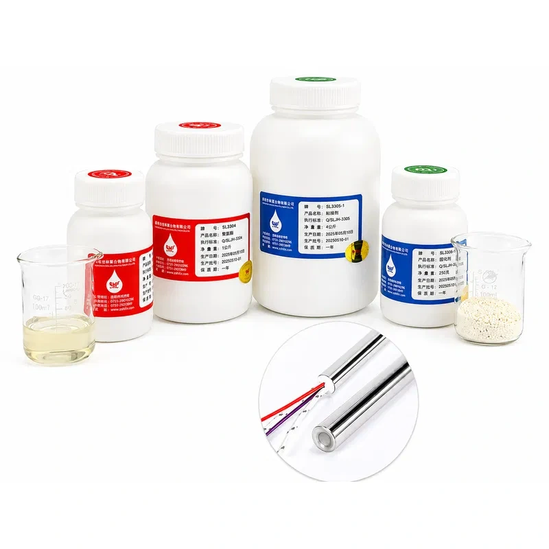
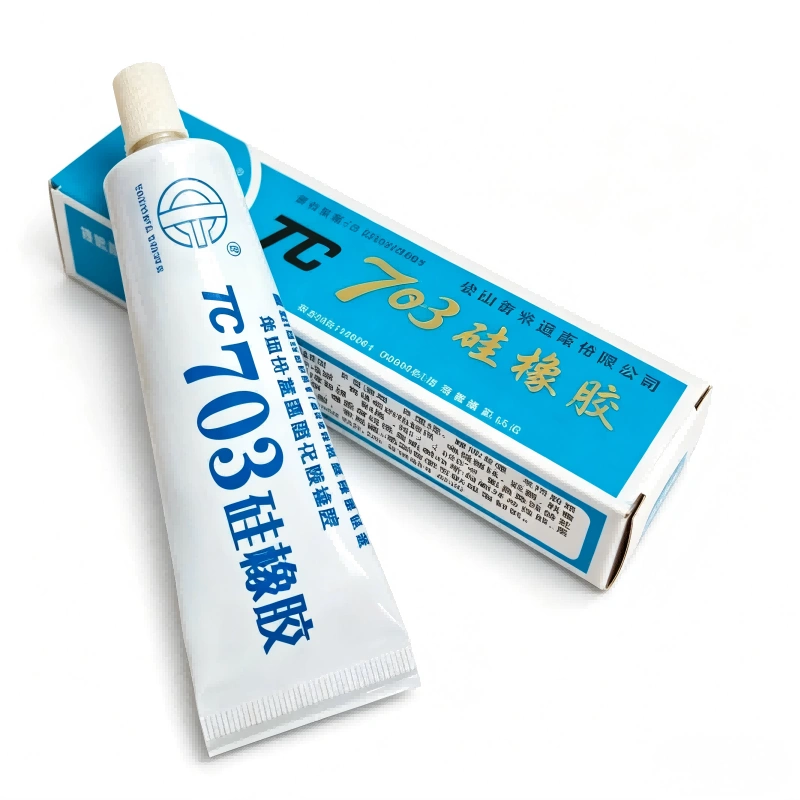
703 Adhesive is a silicone rubber adhesive sealant. It is non-toxic, non-polluting, does not corrode metals, and offers stable and reliable performance.
Electric heat tracing systems for pipe freeze protection, viscosity control and temperature maintenance. Suitable for oil & gas and food industries.
Heat tracing cables — self-regulating and constant wattage — for freeze protection and process temperature maintenance on industrial pipes and tanks.
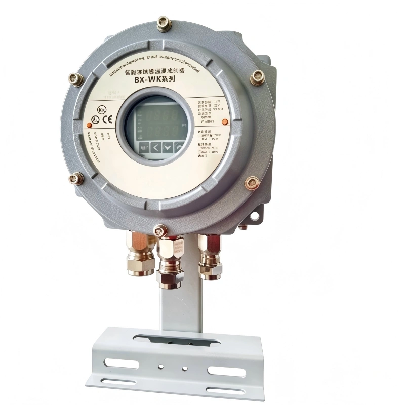
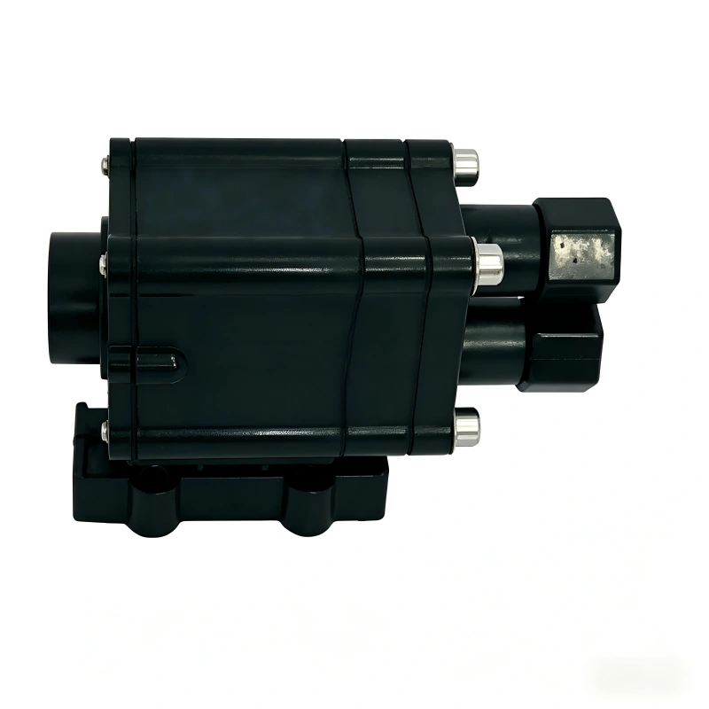
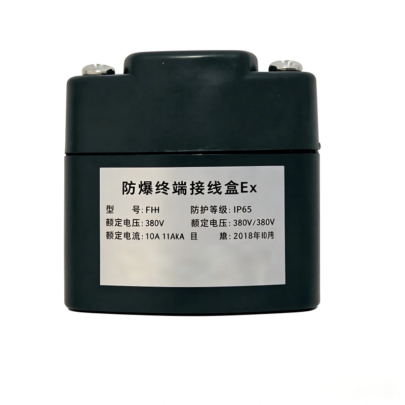
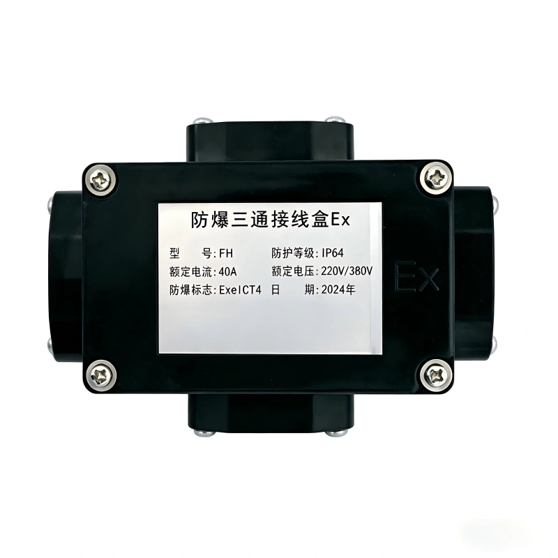
Heat Tracing Cable: Electric Trace Heating for Industrial Pipes and Tanks
Heat tracing (also called electric trace heating or heat trace cable) is an electric resistance heating technology used to maintain or raise the temperature of pipes, tanks, valves and process equipment in industrial plants. Unlike steam or hot-oil tracing, an electric heat tracing system converts electrical energy directly into heat along the entire cable length, installed in direct contact with the surface to be protected and subsequently covered by thermal insulation.
The two primary functional goals of heat tracing are freeze protection, which keeps fluids such as water, fuel or aqueous solutions from freezing inside piping in cold climates, and process temperature maintenance, which preserves the viscosity, flowability or physical state of substances such as heavy oils, asphalt, resins or concentrated chemicals that would otherwise solidify or crystallize below a certain temperature.
Types of Heat Tracing Cable
Self-Regulating Heat Tracing Cable
Self-regulating heat tracing cable is built with a conductive polymer core extruded between two parallel tinned-copper bus wires, encapsulated in a dielectric insulation layer and, in industrial-grade versions, protected by a metallic braid or shield and an outer fluoropolymer jacket. Its defining property is that the polymer matrix changes its electrical resistance as a function of the surrounding temperature: as temperature rises, the polymer expands at the microscopic level, partially interrupting conductive paths between the bus wires and reducing heat output; as temperature falls, the polymer contracts and output increases. This self-limiting behavior lets the cable modulate its own heat output point by point along its length without line thermostats, prevents overheating in already-warm areas (such as those exposed to direct sunlight), and reduces the risk of the cable overheating itself where it crosses over on pipe supports or fittings.
Constant Wattage Heat Tracing Cable
Constant wattage heating cable delivers a fixed heat output per linear meter (W/m), independent of ambient temperature. It is typically manufactured with resistive conductors in parallel or series configuration, insulated with fluoropolymer or silicone, and field-cut to the exact length required. It is the preferred solution when a predictable, uniform heat input is required along the entire circuit length, especially in higher maintenance-temperature applications (above 150 °C / 300 °F), where self-regulating polymer technology loses effectiveness due to conductive-polymer degradation.
Series Resistance / Skin-Effect Heat Tracing
For very long runs (several kilometers per circuit, as in pipeline applications), low-surface-power series resistance systems or skin-effect cables are used, allowing very long circuits to be fed from a single electrical point and drastically reducing the number of junction boxes, transformers and control panels required.
MI (Mineral Insulated) Heat Tracing Cable
For extreme temperature, mechanical stress or direct flame exposure, mineral insulated (MI) heat tracing cable offers the highest power density and thermal resistance on the market, thanks to its compact magnesium oxide (MgO) insulation inside a seamless metallic sheath. See our Heating cables page for a deeper look at this variant.
Technical Comparison Table
|
Cable type |
Typical power range |
Max exposure temperature |
Maintain temperature |
Key advantage |
|
Self-regulating |
5–33 W/m at 50°F |
185–300°F (model-dependent) |
Up to 150°F |
Self-limiting output, field-cuttable |
|
Constant wattage |
10–40 W/m |
Up to 500°F |
Up to 400°F |
Uniform, predictable heat output |
|
Series resistance / skin-effect |
Project-specific design |
Up to 480°F |
Up to 400°F |
Multi-kilometer circuits from one point |
|
MI (mineral insulated) |
High density, custom-engineered |
Up to 1100–1470°F |
Up to 930°F |
Maximum mechanical and thermal resistance |
System Components
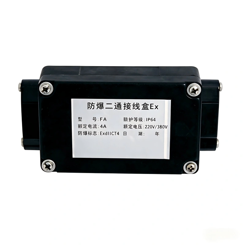
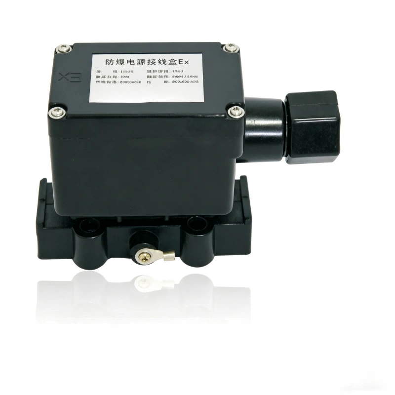
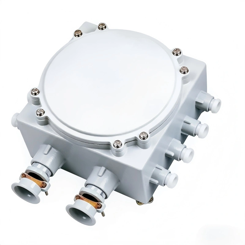
A complete heat tracing system extends well beyond the heating cable itself and includes several critical auxiliary components:
System Design and Power Calculation
Correctly sizing a heat tracing circuit requires calculating the actual heat loss of the pipe or tank being protected, considering:
The result of this calculation determines the cable's linear power output (W/m), the number of circuits required, the power-feed cable gauge, and the required capacity of the control panel and protection devices.
Common Failure Modes and Preventive Maintenance
|
Failure mode |
Typical cause |
Preventive measure |
|
Circuit burnout from overheating |
Cable crossing over itself or another heat source |
Maintain manufacturer's minimum spacing; never cross the cable over itself |
|
Ground fault |
Jacket damage from mechanical abrasion or prolonged UV exposure before insulation is installed |
Visual inspection before insulating; GFEP protection |
|
Loss of electrical continuity |
Mechanical damage during installation or rodent damage |
Additional mechanical protection with conduit on exposed runs |
|
Corrosion at terminations and junction boxes |
Poor sealing against moisture and rainwater ingress |
Certified silicone sealants and cable-specific termination kits |
|
Self-regulating polymer degradation |
Sustained exposure above the model's rated temperature |
Correct model selection based on the process's maximum exposure temperature |
Annual insulation-resistance (megger) and continuity testing is recommended, ideally performed before the onset of the cold season.
Heat Tracing vs. Other Industrial Heating Solutions
|
Solution |
Control precision |
Installation cost |
Maintenance |
Typical application |
|
Electric heat tracing |
High (zone or point control) |
Medium |
Low, no moving parts |
Process pipes, tanks and valves |
|
Steam tracing |
Medium |
High (requires steam network) |
High (steam traps, purging) |
Plants with steam already available |
|
High |
Low |
Low |
Tanks, drums and irregular surfaces |
|
|
Glycol/hot-oil tracing |
Medium-low |
High |
Medium-high |
Large pipe networks with a central boiler |
Manufacturing Process and Quality Control
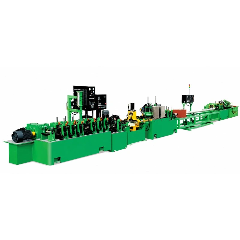
At Heatecx, heat tracing cable manufacturing combines precision extrusion, continuous dimensional control and 100% electrical testing of production output. The process includes extrusion of the polymer core or dielectric insulation over the tinned-copper conductors, braiding or application of the metallic shield, extrusion of the outer fluoropolymer or silicone jacket, and dielectric-strength, insulation-resistance and continuity testing on every spool produced. Each batch undergoes linear power (W/m) testing at multiple reference temperatures to verify compliance with the declared self-regulation curve.
Selection Criteria
|
Factor |
Technical consideration |
|
Process maintenance temperature |
Determines whether self-regulating cable is viable or constant wattage/MI is required |
|
Maximum exposure temperature |
Includes process peaks, steam-out cleaning cycles and direct solar exposure |
|
Area classification |
Hazardous areas require specific Ex certification and reinforced GFEP protection |
|
Pipe length and routing |
Defines the number of circuits, total power and power-feed cable gauge |
|
Available supply voltage |
120V, 208V, 220V, 240V or 480V, depending on the plant's electrical infrastructure |
|
Exposure to corrosive agents |
Determines the outer jacket and shield braid material |
Application Case: Protecting a Dilute Sulfuric Acid Line at a Chemical Plant
A common scenario in the chemical industry illustrates the design logic behind a heat tracing system. An industrial wastewater treatment plant has a 30% dilute sulfuric acid feed line running 85 meters outdoors, between the storage tank and the dosing point. The site's design minimum ambient temperature is 23°F (-5°C), and the process requires keeping the fluid above 50°F (10°C) to prevent partial crystallization and the resulting line blockage.
The selection logic for this type of application combines several of the factors covered in this page: self-regulating cable is chosen over constant wattage, since the required maintain temperature is relatively low and the design takes advantage of the cable's self-limiting response to daily ambient temperature swings. Given the corrosive nature of the transported fluid and outdoor exposure, a fluoropolymer outer jacket with a stainless-steel shield braid is selected instead of tinned copper, to withstand both atmospheric corrosion and a minor process leak should one occur. The circuit is protected by a high-sensitivity GFEP device given the wet, corrosive environment, and is sized with a 15% safety factor above the calculated heat loss to account for outer insulation aging over the system's service life.
This kind of analysis — maintenance temperature, environmental exposure, fluid characteristics and area classification — is exactly what determines the choice between the heat tracing types described on this page in any real project, and it's the same process our team applies when advising on cable selection at Heatecx.
Why Choose Heat Tracing Cable from Heatecx
Heatecx is a direct manufacturer, not a trading intermediary: we design and produce both the machinery used to manufacture heating elements and the raw materials that go into them, giving us end-to-end control over the quality of every heat tracing cable that leaves our Shenzhen facility. This vertical integration — from resistance wire and insulation materials through to the finished product — lets us tailor technical specifications (linear power output, operating voltage, outer jacket material) to the exact requirements of each industrial project, rather than limiting customers to a fixed catalog of standard references.
Our engineering team supports the technical selection process, helping define the right cable type, power output per meter, and the fixation and sealing accessories best suited to each installation's maintenance temperature, area classification and corrosive environment. We work with manufacturing lead times defined and communicated from first contact, and every spool produced undergoes dielectric-strength, insulation-resistance and continuity testing before leaving the factory, as described in the manufacturing process section above.
Self-regulating cable automatically adjusts its heat output based on ambient temperature at every point along its length, while constant wattage cable always delivers the same amount of heat per meter regardless of surrounding temperature.