MoSi2 Heating Elements: Molybdenum Disilicide Heaters
MoSi2 heating elements are ceramic heaters manufactured from molybdenum disilicide, an intermetallic compound that combines the electrical conductivity needed to generate heat with exceptional oxidation resistance at extreme temperatures. Together with silicon carbide (SiC) elements, they form the most widely used family of non-metallic heating elements for industrial and laboratory furnaces operating above 1400°C — a range where conventional metallic alloys (FeCrAl, NiCr) are no longer viable.
Unlike a wound metallic resistance wire, a MoSi2 heating element isn't a generic catalog item; it's a component sized according to operating temperature, furnace atmosphere, required power, and chamber geometry. This page brings together the reference technical information for the entire product category, independent of any specific model or shape.
Composition and Manufacturing Process
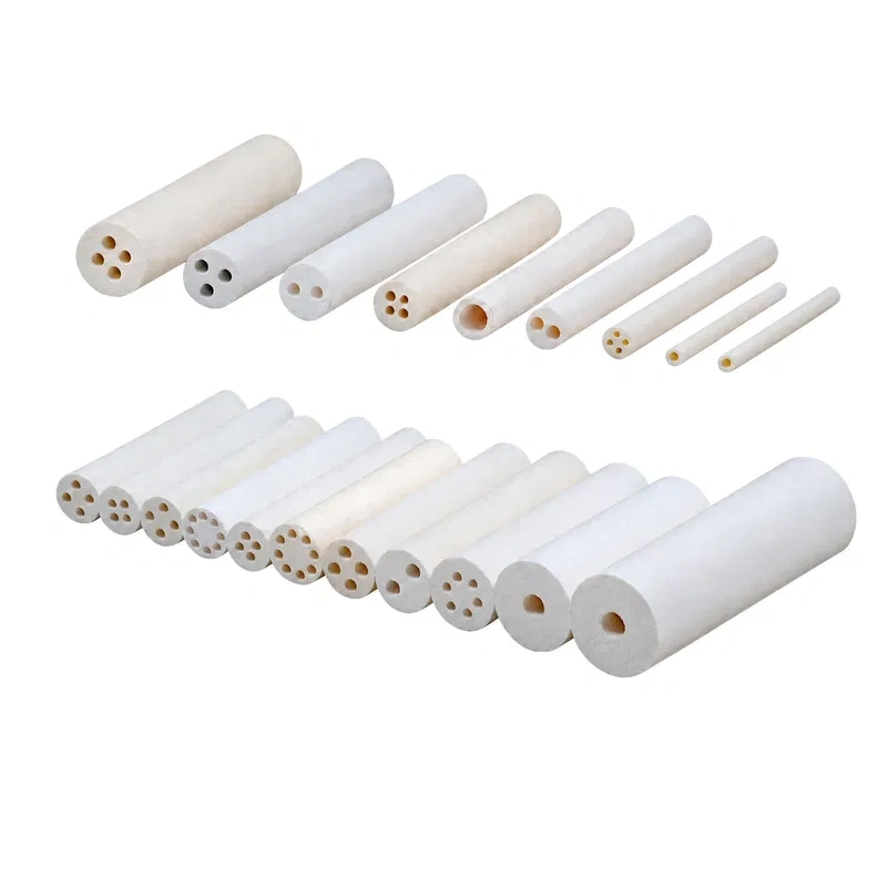
Molybdenum disilicide (MoSi2) is produced through powder metallurgy: Mo and Si powders (or pre-synthesized MoSi2 powder) are blended with a glass-phase additive — typically silicates and borates — that acts as a binder and promotes sintering. The mixture is then compacted and sintered at high temperature under a controlled atmosphere. The result is a cermet-type material that combines the electrical conductivity of a metal with the chemical stability of a technical ceramic, belonging to the same broader material family as the technical ceramics used as supports and insulation in other heating elements.
This glass phase is directly responsible for one of the category's most important properties: when exposed to oxygen at high temperature, the element's surface forms a vitreous silica (SiO2) layer that acts as a self-healing passivation barrier, regenerating itself if mechanically damaged. This layer is what allows a MoSi2 element to retain its effective cross-section and structural integrity over thousands of hours of continuous operation.
Key Technical Properties
|
Property
|
Typical value / behavior
|
|
Max furnace temperature (oxidizing atmosphere)
|
1800–1850°C
|
|
Max element surface temperature
|
Up to 1900°C depending on manufacturer
|
|
Surface power density
|
Up to 20–30 W/cm², roughly 10× a metallic element at 1000°C
|
|
Electrical resistance behavior
|
Low specific resistivity; positive temperature coefficient (PTC) — resistance rises with temperature
|
|
Oxidation protection mechanism
|
Self-regenerating vitreous SiO2 layer
|
|
Mechanical behavior
|
Ceramic material, brittle at room temperature; adequate mechanical strength only when hot
|
|
"Pest oxidation" risk zone
|
Roughly 400–700°C
|
|
Typical service life under correct operation
|
Several thousand hours, with individual replacement possible without shutting down the furnace
|
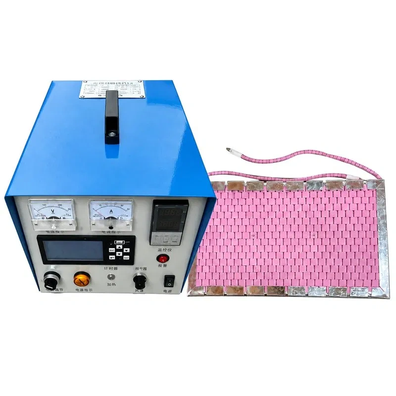
The positive temperature coefficient has an important practical implication for electrical design: cold resistance can be 4 to 8 times lower than hot resistance, so the power supply — typically a regulated low-voltage transformer rather than a direct mains connection — must be sized to absorb this elevated inrush current. This is one of the reasons temperature controllers and the associated power electronics are an integral part of the overall heating system design, not just the element itself.
Available Types and Geometries
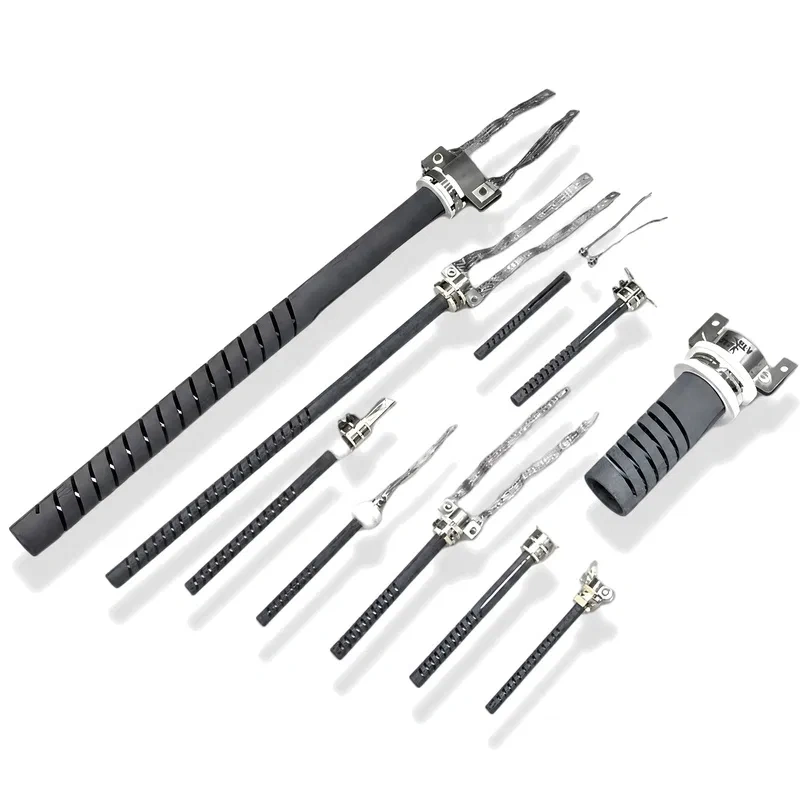
MoSi2 elements are produced in a limited set of standardized geometries, since their brittleness when cold rules out the free-form bending possible with metallic wire. The most common industry configurations are:
- Straight rod elements: the simplest form, a single shank with two cold ends.
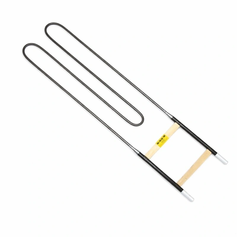
- U-shaped elements: two shanks joined by a curved hot zone, with both cold ends on the same side of the furnace. This is the most widely used configuration due to its ease of installation.
- W-shaped elements: multiple shanks in a single piece, maximizing power density per mounting point.
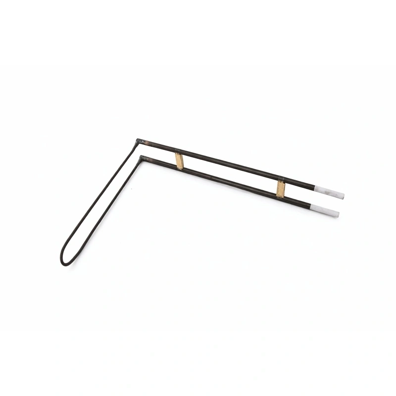
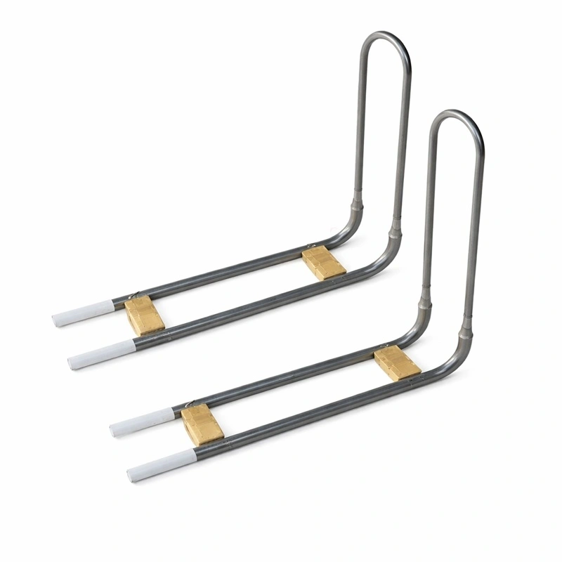
- Right-angle U-shaped / L-shaped elements: variants with an additional 30°, 45° or 90° bend in either the hot or cold zone, designed for furnaces with non-rectangular geometries, corners, or limited access.
- Multi-shank and diffusion cassette elements: for semiconductor process furnaces and applications requiring high thermal precision.
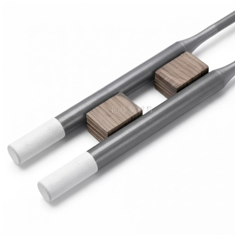
A design feature common to all these geometries is the diameter difference between the hot zone (d1, thinner) and the cold ends (d2, thicker). Being thinner, the hot section concentrates most of the electrical resistance — and therefore the heat generation — while the thicker cold ends stay at a much lower temperature, making them easier to connect via clamps or terminals without active cooling.
Standard Diameter Series (reference)
|
Series (approx. d1/d2)
|
Hot zone diameter
|
Cold end diameter
|
Typical use
|
|
3/6
|
3 mm
|
6 mm
|
Laboratory furnaces, small loads
|
|
6/12
|
6 mm
|
12 mm
|
Medium-sized industrial furnaces
|
|
9/18
|
9 mm
|
18 mm
|
High-power, continuous-production furnaces
|
Exact dimensions, hot-zone length (Le), and cold-end length (Lu) vary by manufacturer and are selected based on total power requirements and the furnace chamber's internal dimensions.
Industrial Applications
MoSi2 heating elements are used in processes where temperature, chemical stability, or thermal precision requirements rule out other technologies:
- Technical ceramics and refractories: sintering of alumina, zirconia, porcelain, and other materials requiring firing temperatures above 1500°C.
- Glass: melting, annealing, and forming of optical glass, glass fiber, and display glass.
- Magnetic materials: sintering of ferrites and other high-tech electronic components.
- Metallurgy: heat treatment, metal powder sintering, brazing, and casting processes in the automotive, aerospace, and tooling industries.
- Semiconductors: diffusion, oxidation, and LP-CVD furnaces, where temperature stability and freedom from contamination are critical.
- Research and laboratory use: muffle furnaces and experimental high-temperature setups.
Selection Criteria
|
Process criterion
|
Technical guidance
|
|
Furnace temperature above 1600°C
|
MoSi2 is the preferred option over SiC elements; see the detailed comparison in our SiC vs MoSi2 guide
|
|
Oxidizing or air atmosphere
|
Ideal condition; the SiO2 layer forms and regenerates correctly
|
|
Inert or low-oxygen atmosphere
|
Requires specific validation; risk of pest oxidation in the 400–700°C range if not passed through quickly
|
|
Need for replacement without stopping production
|
MoSi2 allows hot-swapping, minimizing downtime
|
|
Furnace with corners or non-rectangular geometry
|
L-shaped or right-angle U elements
|
|
Fast, frequent heating cycles
|
MoSi2 tolerates rapid thermal cycling without significant degradation
|
|
Tight budget, temperature ≤1600°C
|
Evaluate SiC as a lower-cost alternative
|
Connection, Installation and Start-Up
The cold ends of the element are connected using flexible aluminum clamps or straps designed to maintain good electrical contact without transmitting mechanical stress to the ceramic material, which is brittle at room temperature. Avoiding impacts, bending, or sudden thermal shock during installation is essential. Power must be supplied through a regulated low-voltage transformer — typically via temperature controllers with phase-angle or thyristor-based power control — capable of handling both the cold-start inrush current and the progressive power adjustment as the element heats up.
Service Life and Maintenance
The electrical resistance of a MoSi2 element tends to increase gradually over its service life, as the protective oxide layer thickens and slightly reduces the effective conductive cross-section. This behavior is predictable and gradual, which — unlike other technologies — allows new and used elements to be connected in series within the same furnace without compromising thermal uniformity, provided the supply voltage is periodically readjusted.
The main threat to service life isn't wear at operating temperature, but slow thermal cycles that keep the element too long in the accelerated-oxidation risk zone (roughly 400–700°C), where the protective layer hasn't yet stabilized. A sound start-up protocol — heating relatively quickly through that range — along with the procedures described in our guide on common causes of heating element failure, significantly extends operating life. For a broader view of the factors that determine the durability of any industrial heating element, see our article on the lifespan of industrial heaters.
MoSi2 vs. Other Heating Technologies
|
Aspect
|
MoSi2
|
SiC
|
Metallic alloy (FeCrAl/NiCr)
|
|
Max temperature
|
Up to 1850°C
|
Up to 1600°C
|
Up to approx. 1400°C
|
|
Temperature coefficient
|
Positive (PTC)
|
Negative over time (aging)
|
Relatively stable
|
|
Brittleness
|
High when cold
|
High when cold
|
Low, ductile
|
|
Power density
|
Very high
|
High
|
Medium
|
|
Relative cost
|
High
|
Medium
|
Low
|
A full breakdown of advantages, compatible atmospheres, and use cases is covered in more depth in our blog article, SiC vs MoSi2 Heating Elements: The Complete Guide for Industrial Furnace Operators.