Introduction
When a heating element fails in the middle of a production run, it’s almost never an isolated accident — it’s the visible endpoint of a degradation mechanism that has been developing silently for weeks, sometimes months. For a plant that depends on furnaces, drying ovens, or heat-treatment lines, that failure means more than the cost of the replacement part: it means hours of lost production, batches that may fall out of specification, and in some cases, safety risks for maintenance staff working near live equipment.
Heating elements — whether coiled resistance wire, tubular elements filled with magnesium oxide, or ceramic materials like silicon carbide — are engineered to run reliably for thousands of hours. But that reliability depends on certain design, installation, and operating conditions being respected. When those conditions are violated, the resulting failure leaves recognizable fingerprints — a specific discoloration, a localized deformation, a fracture at one particular point — that an experienced maintenance engineer can often diagnose just by looking at the removed element.
This article walks through the seven most common failure mechanisms in industrial heating elements in depth, explaining not just what happens but why it happens at a physical and metallurgical level, so you can diagnose the real root cause of a recurring failure instead of simply replacing the symptom.
1. Oxidation and Breakdown of the Protective Oxide Layer
Most resistance wire alloys — iron-chromium-aluminum (FeCrAl, commercially known as Kanthal) and nickel-chromium (NiCr, Nichrome-type) — survive temperatures of 1000–1400°C thanks to a very specific mechanism: the first time the metal is heated, chromium and aluminum in the alloy migrate to the surface and react with atmospheric oxygen to form a thin, dense oxide layer (Cr₂O₃ for NiCr, Al₂O₃ for FeCrAl). This layer, only a few microns thick, is the only thing standing between the base metal and continuous attack from atmospheric oxygen. You can see the range of alloys built around this mechanism in our resistance wires catalog.
The problem is that this layer isn’t static. Every time the element goes through a heating and cooling cycle, the oxide and the base metal expand and contract at different rates — since they have different thermal expansion coefficients — which generates microcracks in the protective layer. Under normal conditions, the element “self-heals” these cracks by forming fresh oxide as soon as it heats up again. But if thermal cycles are too frequent, too abrupt, or if the atmosphere contains contaminants that interfere with oxide regeneration (sulfur compounds, chlorine, zinc vapors), the layer stops repairing itself in time. The base metal is exposed, oxidizes uncontrollably, and loses cross-sectional area right at that point — and since electrical resistance is inversely proportional to cross-sectional area, that spot starts running hotter than the rest of the element, which accelerates its own oxidation even further until it burns through.
This mechanism explains why elements running on constant on/off cycling (common in domestic applications or furnaces with aggressive on-off control) tend to fail sooner than elements operating at stable temperature under well-tuned PID controllers: it isn’t the peak temperature that kills them, it’s the frequency of thermal cycling.
How to prevent it in practice:
New elements should go through an initial conditioning period — a slow, controlled first firing, typically following the ramp curve recommended by the manufacturer — that allows a uniform oxide layer to form before exposing the element to full load. Skipping this step is one of the most common causes of premature failure in new installations. It’s also worth auditing furnace atmosphere: process oils, residual lubricants, or coated materials that release chlorine or sulfur when heated can neutralize the protective layer within hours, even on high-quality elements.
2. Hot Spots: The Failure That Feeds on Itself
A hot spot is almost always the final stage of another problem, not the problem itself. It occurs when one localized section of the element reaches a temperature notably higher than the rest — sometimes 100–200°C higher — visible as a brighter, more incandescent zone during operation.
Several paths lead to a hot spot, but they all share the same feedback loop: once a section carries more local resistance (from oxidation, reduced cross-section, or poor electrical contact), that section generates more heat via the Joule effect; the extra heat accelerates local oxidation; the oxidation further reduces cross-section; and local resistance keeps climbing. It’s a self-reinforcing cycle that, without intervention, always ends in a burnout at that exact point.
The most frequent triggers that kick off this cycle are insufficient or unevenly distributed support (which causes coils in a wound element to sag and touch each other, creating a partial short-circuit), inadequate spacing between coil turns (which prevents even dissipation of radiant heat), and loose or corroded terminal connections, which act as an added resistance point right at the end of the element.
How to prevent it in practice:
The element’s ceramic support must match the coil spacing specified by the manufacturer exactly; tightening that spacing to “stretch” an element during an improvised repair is a direct recipe for a hot spot within weeks. Terminal connections should be inspected periodically — with thermal imaging where possible — since a connection that’s starting to degrade shows a local temperature rise long before it fails visibly.
3. Thermal Shock: When the Speed of the Change Matters More Than the Temperature
Thermal shock is a fundamentally different mechanism than oxidation: here it’s the material’s mechanical structure that fails, not its surface chemistry. It happens when one part of the element heats or cools much faster than the rest, generating internal stresses from the differential expansion between zones. If those stresses exceed the material’s mechanical strength, a crack forms.
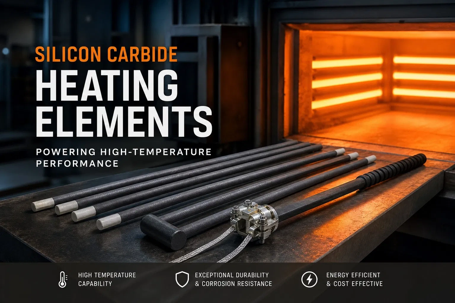
This risk is especially high in ceramic and semiconductor materials used as high-temperature heating elements, such as silicon carbide (SiC) and molybdenum disilicide (MoSi2). These materials withstand working temperatures far above metallic alloys — up to 1700°C for MoSi2 — precisely because they don’t depend on a protective oxide layer the way NiCr or FeCrAl do, but on their own crystalline structure. That same structure, however, is more rigid and less ductile than a metal, making these elements considerably more brittle when facing sudden thermal gradients. A SiC element pulled from a furnace at 1300°C and exposed directly to a cold air draft can fracture within seconds — a thermal jolt that would barely affect a Kanthal resistance wire.
How to prevent it in practice:
The key variable is the temperature ramp, not just the final temperature. Programmable controllers should be configured with heating and cooling rates matched to the material type — typically 5 to 10°C per minute for ceramic elements, versus much more aggressive ramps that a metallic wire can tolerate. It’s equally important to avoid opening furnace doors while the element is at operating temperature, and to never bring a hot element into contact with cold liquids or parts.
4. Mechanical Damage and Improper Installation
Unlike the three mechanisms above, this one doesn’t depend on how the equipment is operated but on what happens before the element even enters service: transport, storage, and installation. Ceramic and ceramic-metal composite elements are particularly vulnerable because they combine rigidity with fragility — they handle the thermal load they were designed for very well, but tolerate bending, impact, or excessive terminal torque during assembly very poorly.
It’s common to find failures that, upon inspection, trace back to careless installation months earlier: an internal crack that didn’t break the element immediately but propagated slowly with every thermal cycle until it failed at a moment that appears — wrongly — disconnected from its real cause.
How to prevent it in practice:
Following the manufacturer’s handling instructions to the letter, using appropriate lifting equipment for large or heavy elements, and visually inspecting every element for cracks before installation are simple measures that prevent a surprisingly large share of the failures labeled “premature” and wrongly blamed on manufacturing defects.
5. Chemical Contamination and Aggressive Atmospheres
The atmosphere inside a furnace or heating chamber is not a secondary factor — in many industrial processes, it’s the variable that, together with thermal cycling, shortens an element’s real service life the most compared to its theoretical lab-tested lifespan. Sulfur compounds present in process oils and lubricants, chlorine from certain plastics or degreasers, zinc vapors from galvanized parts processed in the same furnace, and residual moisture in specific alloy systems can chemically attack the element’s surface in ways that simple air oxidation does not.
The result is usually localized, aggressive corrosion, quite different in appearance from uniform aging-related oxidation: dark staining, pitting, or accelerated deterioration concentrated exactly where contaminant vapors build up inside the chamber.
How to prevent it in practice:
Ensuring proper ventilation of the process chamber, avoiding the introduction of coated or oil-residue materials without prior degreasing, and — where the process allows — selecting the element alloy based on the specific process atmosphere and not just the temperature, are the most effective measures against this failure mode.
6. Electrical Overload
When a heating element operates above its rated voltage, current, or watt density, it generates more heat internally than it was designed to dissipate. The result is an acceleration of every mechanism described above at once: oxidation advances faster, hot-spot risk rises, and service life drops off non-linearly — doubling an element’s watt density can cut its lifespan by an order of magnitude, not just by half.
The most common causes of overload are rarely design errors in the element itself, but problems upstream: a power supply mismatched against the manufacturer’s specifications, control-system faults that allow unexpected voltage or current spikes, or an undersized element selected for a heat load the process actually demands to be higher.
How to prevent it in practice:
Verifying that the power supply exactly matches the element’s rated specifications, sizing the element based on the process’s real heat load (not an optimistic estimate), and implementing a reliable temperature control and monitoring system — such as our temperature controllers — are the three measures with the greatest impact on real-world service life.
7. Poor Terminal Connections
Alongside poor mechanical support, this is one of the most underrated causes of failure, precisely because the problem isn’t in the element itself but in its electrical connection point. A loose, corroded, or improperly sized terminal adds electrical resistance right at the contact point, and that extra resistance generates localized heat capable of damaging both the terminal and the element material immediately adjacent to it — often the weakest zone in the entire installation, since it combines thermal stress with the mechanical stress of the connection itself.
How to prevent it in practice:
Periodic inspection of connections — checking torque and the absence of corrosion — and prompt replacement of any hardware showing signs of degradation are low-cost measures with an outsized return in terms of reliability.
Extending Element Service Life: An Integrated View
Most of the time, no heating element fails from a single isolated cause; the usual pattern is a combination of two or three factors reinforcing each other — for example, a slightly contaminated atmosphere accelerating oxidation, combined with aggressive thermal cycling that also causes microcracking in the protective layer. That’s why the most effective prevention strategy isn’t attacking a single mechanism, but building a complete process: properly conditioning new elements, controlling furnace atmosphere, minimizing unnecessary thermal cycling, respecting recommended temperature ramps, regularly inspecting support structures and connections, precisely sizing each element for the application’s actual load, and training maintenance staff on correct handling during installation.
There’s also a factor that originates even before the element reaches the plant, in the manufacturing of the component itself. When an element is built from cold-formed metal tubing — for example, via rolling or diameter reduction to match the tube to the final design — that forming process work-hardens the metal and generates internal stresses. If the tube is then bent under those conditions without a prior annealing step to restore ductility, invisible microfractures appear at the bend points. These microfractures don’t break the element immediately, but they become the starting point of a premature failure weeks or months after startup — a failure the plant perceives as a “manufacturing defect” but which actually originates in a process step skipped before final assembly.
Working with a supplier who understands this entire chain — from alloy selection to the thermal treatment of the tube before bending — and who provides consistently high-quality raw materials measurably reduces the frequency of failures that, viewed from the plant floor, look random but almost never are.
Frequently Asked Questions
What is the average lifespan of a heating element? It varies enormously depending on material, operating temperature, process atmosphere, and duty cycle. Under demanding industrial conditions — frequent cycling, contaminated atmospheres — it can be as short as a few months; in well-controlled applications with stable temperature and a clean atmosphere, the same materials can exceed several years of continuous service.
Can a heating element be repaired after a hot spot forms? In practice, not reliably. Once a hot spot has caused visible deformation or localized accelerated oxidation, that section is structurally compromised — even if the element keeps running for a while, complete failure is usually just a matter of time, and replacement is safer than attempting a repair.
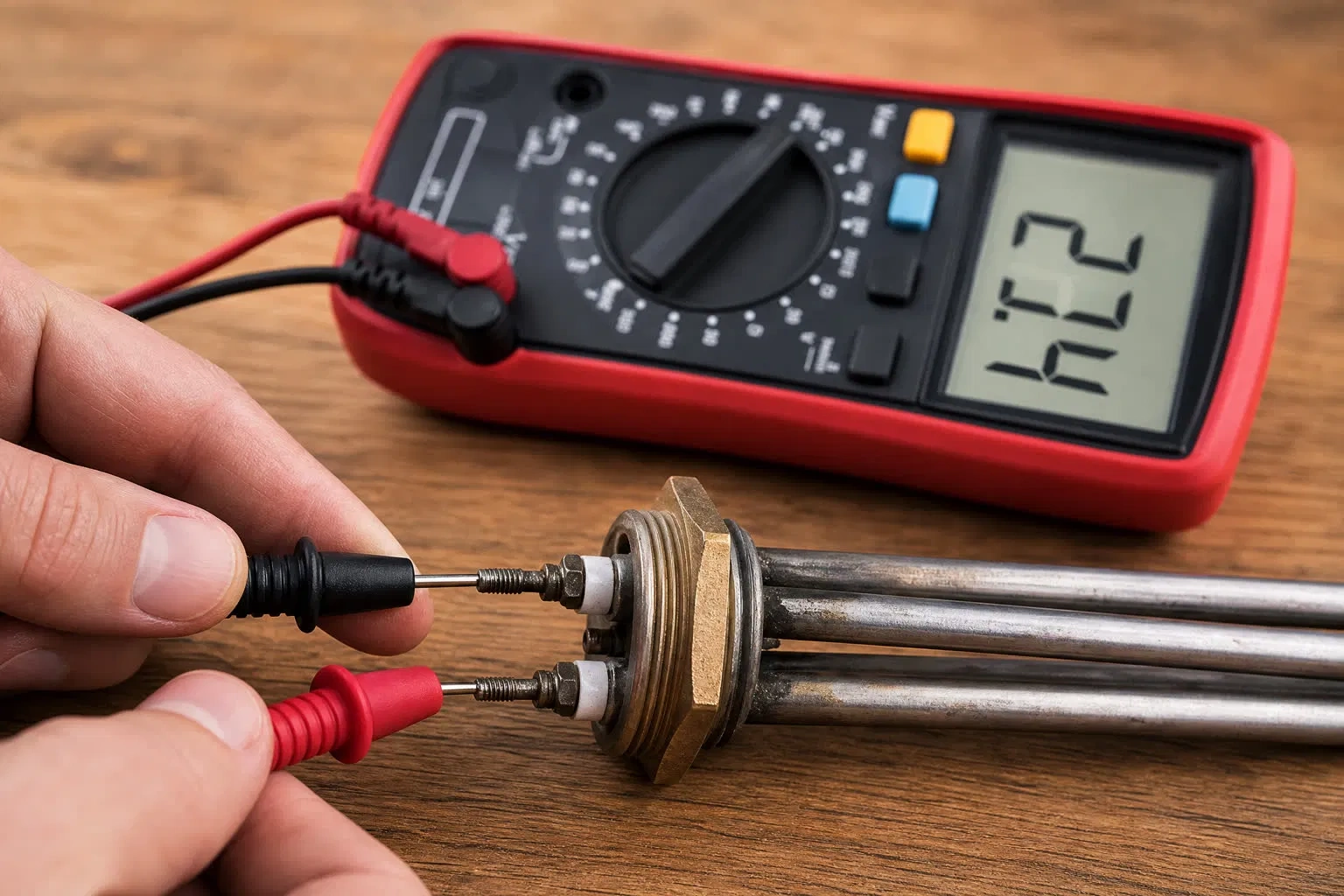
How can I tell if a heating element is about to fail? The most reliable signs are visible discoloration or sagging, localized spots that glow brighter than the rest of the element during operation, a gradual increase in the element’s measured electrical resistance, and increasingly irregular or slow heating performance when trying to reach the setpoint temperature.
Does the type of alloy really affect resistance to failure? Yes, significantly. FeCrAl alloys generally offer better oxidation resistance at the higher end of the temperature range, while NiCr alloys provide greater ductility and mechanical strength at moderate temperatures, making them more tolerant of handling and installation. The right choice depends on both the working temperature and the specific atmosphere of the process.
Conclusion
Most heating element failures aren’t random events — they’re the predictable result of identifiable mechanisms (oxidation, hot spots, thermal shock, atmospheric contamination, electrical overload, mechanical damage, or poor connections) that frequently combine with one another. Understanding these mechanisms at a physical level, rather than as a simple list of symptoms, is what allows a plant to move from reactively replacing elements to designing a genuine preventive maintenance process — one capable of reducing both unplanned downtime and the total cost of ownership of the installation over the long term.
If you’re sourcing heating elements, resistance wire, or raw materials for heating element manufacturing with consistent quality guarantees, contact our technical team to discuss the right specifications for your application.