Silicon Carbide (SiC) Heating Elements: High-Temperature Resistors for Industrial Furnaces
Silicon Carbide (SiC) heating elements, internationally known as Globar elements, are non-metallic ceramic heating components manufactured from ultra-high-purity silicon carbide through bonded extrusion followed by recrystallization sintering at temperatures above 2000°C. This process produces a dense, self-supporting polycrystalline structure with hardness approaching that of corundum, setting it apart from conventional metallic elements such as nichrome (Ni-Cr) or Fe-Cr-Al alloy wire.
Unlike metallic resistors, silicon carbide is a ceramic semiconductor: its electrical behavior does not follow Ohm's law linearly and instead exhibits a pronounced positive temperature coefficient (PTC), particularly during cold start-up. This characteristic is a decisive factor when engineering the power supply and control circuitry of any furnace that incorporates SiC elements.
Its combination of chemical stability, low thermal expansion, and outstanding thermal shock resistance makes it the benchmark heating element for continuous industrial processes requiring high operating temperatures and a long service life in oxidizing atmospheres.
Composition and manufacturing process
Heatecx SiC elements are manufactured from selected-grain green silicon carbide, with SiC content typically between 90% and 98% depending on grade and market segment. The standard industrial process includes:
- Mixing and bonded extrusion: SiC grain is combined with binders and extruded into rod form, establishing the element's base geometry.
- Recrystallization sintering: the green rod is fired above 2100°C in a controlled atmosphere, bonding the SiC grains together without a liquid phase and virtually eliminating open porosity.
- Cold-end metallizing: the cold ends are impregnated with metallic silicon or coated to lower their resistivity, creating the characteristic resistance gradient between the hot zone and the terminals.
- Machining and dimensional control: diameter grinding, threading, or spiral-groove cutting depending on element type, followed by cold-resistance verification prior to batch matching.
Typical technical properties
|
Property
|
Typical value
|
|
Maximum element temperature
|
Up to 1625°C (varies by design and loading density)
|
|
Recommended continuous operating temperature
|
1400–1550°C
|
|
Density
|
2.5–2.7 g/cm³
|
|
Hardness (Mohs scale)
|
~9
|
|
Coefficient of thermal expansion
|
~4.5 x 10⁻⁶ /°C
|
|
Resistivity at room temperature
|
High, decreasing with temperature up to ~800°C (initial NTC behavior)
|
|
Behavior at service temperature
|
Positive temperature coefficient (PTC) — resistance rises with use
|
|
Thermal shock resistance
|
High
|
|
Chemical stability
|
Excellent in oxidizing atmospheres; sensitive to reducing atmospheres and alkaline vapors
|
|
Typical service life
|
5,000–10,000 hours under proper operating conditions, depending on load density and atmosphere
|
Technical note on aging: SiC undergoes a gradual, irreversible increase in electrical resistance throughout its service life, typically on the order of 5–10% every few thousand operating hours under normal conditions. This inherent behavior requires power supply systems with voltage reserve (tapped transformers or SCR power controllers) to compensate for the loss of delivered power as the element ages.
Available geometries and configurations
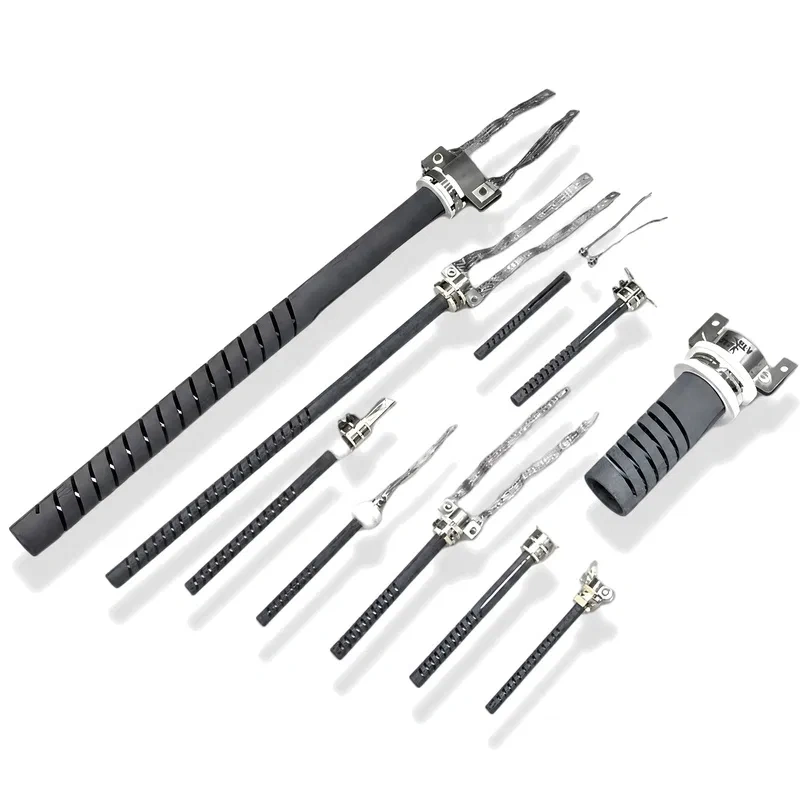
Silicon carbide elements are manufactured in multiple geometries to fit different furnace chambers and power-density requirements:
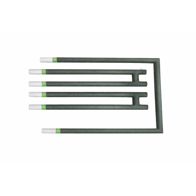
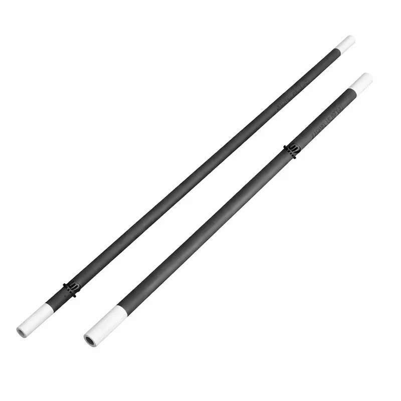
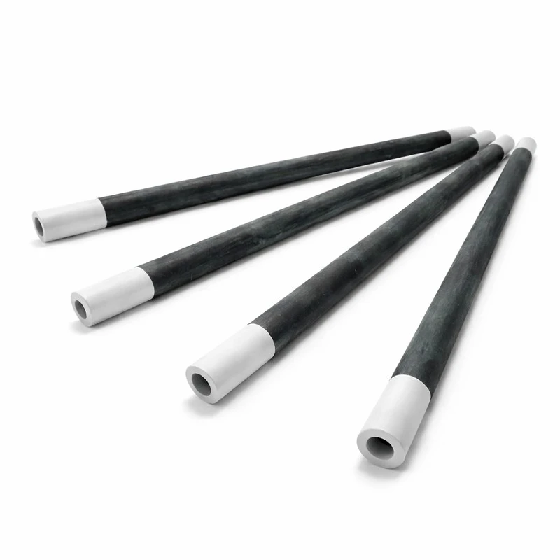
- Straight rod type: the simplest configuration, with cold terminals at both ends.
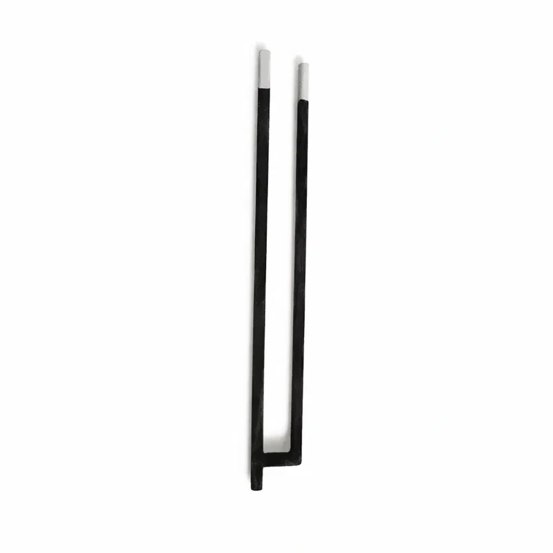
- H-Type: dual heating zone with both terminals on the same side, designed for single-terminal heating in rotary and glass furnaces. See the Silicon Carbide H-Type Heater.
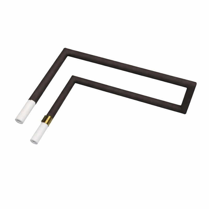
- U/L angle type: an angular design engineered as a direct replacement for electrical or alloy wire in crucible melting and rotary furnaces, optimizing heat distribution in non-conventional geometries.
- Double heating zone: allows independent thermal control of two sections, common in glass processes with dual channels.
- Helical/spiral-cut configuration: increases the effective hot-zone length within a compact space, raising power density per unit length.
Comparison with other ceramic heating elements
|
Criterion
|
Silicon Carbide (SiC)
|
Molybdenum Disilicide (MoSi2)
|
Ni-Cr / Fe-Cr-Al wire
|
|
Maximum temperature
|
Up to 1625°C
|
Up to 1850°C
|
1100–1400°C
|
|
Electrical behavior
|
Ceramic semiconductor (PTC)
|
Metal-ceramic (cermet)
|
Linear metallic
|
|
Aging
|
Gradual resistance increase
|
Stable after SiO2 layer forms
|
Progressive wire oxidation
|
|
Brittleness
|
High (brittle when cold)
|
High (brittle when cold, ductile when hot)
|
Low (ductile)
|
|
Compatible atmospheres
|
Oxidizing; sensitive to reducing
|
Oxidizing
|
Oxidizing and some reducing
|
|
Typical application
|
Ceramic kilns, glass, industrial heat treatment
|
Laboratory furnaces and very high-temperature processes
|
Domestic and mid-temperature industrial furnaces
|
For applications exceeding 1625°C, or where a more stable electrical resistance over time is required, Molybdenum Disilicide (MoSi2) heating elements are the technical reference alternative within the Heatecx catalog.
Industrial applications
SiC elements are the heating element of choice in sectors where temperature, chemical stability, and mechanical robustness are critical:
- Ceramic industry: firing of porcelain, tiles, refractories, and technical ceramics in tunnel and batch kilns.
- Glass industry: melting, annealing, and forming, including channel furnaces heated by H-type or dual-zone elements.
- Metal heat treatment: annealing, quenching, and tempering in muffle and controlled-atmosphere furnaces.
- Metallurgy and foundry: crucible and rotary furnaces for non-ferrous metal melting.
- Electronics and semiconductors: sintering furnaces and high thermal-purity processes.
- R&D laboratories: test furnaces requiring repeated thermal cycling and dimensional stability.
Selection criteria
|
Parameter to define
|
Technical consideration
|
|
Process temperature
|
Determines the working range (kept below the element's maximum limit with a safety margin)
|
|
Furnace atmosphere
|
Oxidizing is recommended; reducing atmospheres or alkaline vapors require prior evaluation
|
|
Load density (W/cm²)
|
Determines expected service life and aging rate
|
|
Chamber geometry
|
Determines whether a straight, H, U/L, or dual-zone configuration is required
|
|
Power supply system
|
Must include voltage reserve to compensate for element aging
|
|
Thermal cycling (continuous vs. intermittent)
|
Frequent heating/cooling cycles require higher thermal shock tolerance
|
Standard dimensional ranges
Although every geometry can be custom-manufactured, the SiC heating element market generally operates within the following reference ranges, common across leading manufacturers in the sector:
|
Dimensional parameter
|
Typical range
|
|
Hot-zone diameter
|
10–55 mm
|
|
Cold-end (terminal) diameter
|
Larger than the hot-zone diameter (reduces current density at the cold end)
|
|
Hot-zone length
|
Up to 4,200 mm
|
|
Overall element length
|
100 mm to 6,000 mm
|
|
Dimensional tolerance
|
±2–3% of nominal dimensions
|
|
Cold-resistance tolerance
|
Typically ±5–10% within a single production batch (matching)
|
The ratio between hot-zone diameter and cold-end diameter — known as the hot-to-cold ratio — is one of the most decisive design parameters: the higher this ratio, the greater the power density that can be concentrated in the hot zone without overheating the electrical connection points.
Electrical design and power control
The semiconductor nature of SiC calls for an electrical design approach different from that of a conventional metallic resistor:
- Voltage reserve: since element resistance increases with aging, the supply transformer must be sized with multiple voltage taps that allow the applied voltage to be increased over the element's service life without exceeding its rated power limit.
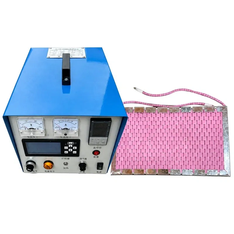
- SCR (thyristor) control: in more demanding installations, solid-state power controllers allow continuous adjustment of the effective applied voltage, compensating for both aging and resistance variation between elements on the same circuit.
- Batch matching: elements operating on the same electrical circuit — in series or in parallel — should be selected within the same cold-resistance range to avoid uneven current distribution and the resulting accelerated aging of lower-resistance elements.
- Series vs. parallel configuration: series wiring promotes more uniform current across elements, while parallel wiring requires stricter matching control to prevent a lower-resistance element from absorbing a disproportionate share of the total power.
- Cold-end overvoltage protection: the metallized ends have much lower resistance than the hot zone; incorrectly sized clamps or connections can create localized hot spots due to contact resistance.
Common failure modes
|
Failure mode
|
Typical cause
|
Observable indicator
|
|
Thermal shock fracture
|
Heating/cooling cycles that are too fast or uneven
|
Visible cracking, sudden element breakage
|
|
Accelerated cold-end oxidation
|
Poor electrical contact, localized overheating
|
Discoloration or visible deterioration at the connection zone
|
|
Premature aging
|
Excessive load density for the operating atmosphere
|
Abnormal resistance increase over a short period
|
|
Chemical attack
|
Reducing atmospheres or presence of alkaline/metallic vapors
|
Thinning or surface corrosion of the hot zone
|
|
Hot spot
|
Incorrect matching of elements on the same circuit
|
Zone of more intense glow or localized premature failure
|
|
Mechanical breakage during handling
|
Impacts or bending during transport, storage, or installation
|
Visible cracks or chipping before start-up
|
Installation and mounting
Installing SiC elements in the furnace chamber requires observing a set of technical criteria to preserve expected service life:
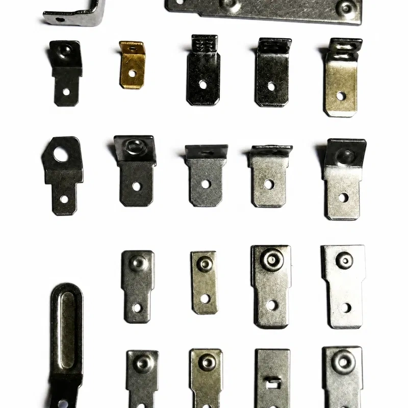
- Cold-end clamping: use clamps or contact terminals with a broad contact surface, avoiding concentrated pressure points that could crack the ceramic material.
- Thermal clearance: adequate expansion clearance must be left between the element and the furnace structure, given the material's coefficient of thermal expansion.
- Positioning relative to the load: the distance between the element and the workpiece or material being heated affects both energy efficiency and thermal uniformity within the chamber.
- Connection wiring: must be sized to withstand cold start-up current, which is higher than steady-state current once operating temperature is reached, due to the material's initial NTC behavior.
- Pre-commissioning verification: measure the cold resistance of each element before final connection, to confirm it falls within the circuit's matching range.
Quality control and certifications
Every batch of SiC elements manufactured by Heatecx undergoes a verification process that includes:
- Dimensional inspection of diameters, lengths, and straightness against specified tolerances.
- Cold electrical resistance measurement of each unit, with classification and grouping into matching ranges prior to shipment.
- Visual inspection of the ceramic surface to detect microcracks, surface porosity, or metallizing defects at the terminals.
- Manufacturing under ISO 9001 quality management systems, with batch traceability from raw material to finished product.
Packaging and transport
Given their fragility as a ceramic material and their high value as an industrial component, each SiC element is individually wrapped in protective materials (foam, bubble wrap) inside padded, immobilized inner boxes. Outer packaging is reinforced with high-strength wooden crates or corrugated cardboard boxes, filled with cushioning material and clearly labeled "FRAGILE" with orientation arrows, in compliance with international freight regulations.