When an injection mold needs to keep a thermoplastic molten right at the nozzle tip, in a gap of just a few millimeters between cavities, no conventional tubular heater fits. That exact spot — the runner that keeps the plastic molten from the manifold to the cavity — is where mini-tubular heaters come in, also known across the industry as micro-tubular heaters, hot runner heaters, or gate heaters. All of these terms describe essentially the same type of heating element: a miniaturized sheathed tubular resistor designed to be installed directly on nozzles and manifolds of hot runner systems in injection molds, where space is the most severe constraint and thermal precision is non-negotiable.
Hot Runner vs. standard tubular vs. cartridge heater
Before getting into construction detail, it helps to place the mini-tubular heater against the two other sheathed-heater families it’s often confused with:
| Feature | Hot Runner Heater | Standard Tubular Heater | Cartridge Heater |
| Typical cross-section | 1.3 – 4.3 mm | 8 – 16 mm | 6.5 – 25 mm (diameter) |
| Section geometry | Circular, oval, or rectangular | Circular, oval on request | Circular |
| Common configuration | Coiled or straight | Straight, bent, or serpentine | Straight, axial insertion |
| Main use | Hot runner nozzles and manifolds | General liquid/air/industrial heating | Molds, platens, drilled metal blocks |
| Thermal inertia | Low | Medium-high | Medium |
| Integrated thermocouple | Common (type J) | Uncommon | Occasional |
| Typical power density | High per unit surface | Medium | High, axially concentrated |
| Minimum installation clearance | Millimeters between elements | Centimeters | Diameter of the insertion bore |
A hot runner heater doesn’t replace a standard tubular or a cartridge heater: it fills the specific niche where available space is so tight that neither of the other two geometries can physically be installed without compromising the mold design.
What sets it apart from a conventional tubular heater
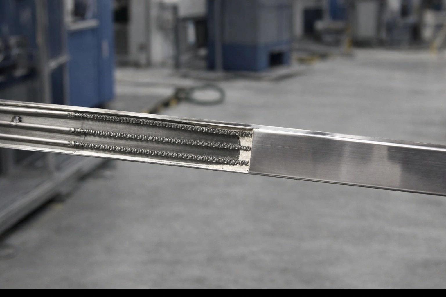
The internal construction of a mini-tubular heater follows the same principle as any sheathed tubular resistor: a resistive wire (typically Ni-Cr 80/20 alloy) sits at the center of a metal tube, surrounded by compacted magnesium oxide (MgO) that acts as both electrical insulator and thermal conductor. What changes radically is the scale. While a standard industrial tubular heater may run 8 to 16 mm in cross-section, a mini-tubular heater operates in cross-sections between 1.3 and 4.3 mm, with wall thicknesses as low as 1.4 to 2.3 mm in oval or rectangular profiles. This miniaturization isn’t just about shrinking a familiar product: every millimeter removed from the diameter forces a rethink of power density, resistive wire life, and the tube’s ability to conduct the generated heat to the contact surface without localized hot spots.
The result is an element with much lower thermal inertia than a conventional tubular heater. That has a direct practical consequence on the molding process: the nozzle responds faster to temperature controller adjustments, cutting the stabilization time after a color, resin, or cycle-speed change, and allowing tighter control of the thermal profile across the entire hot runner line.
Configurations: coiled, straight, and with an integrated thermocouple
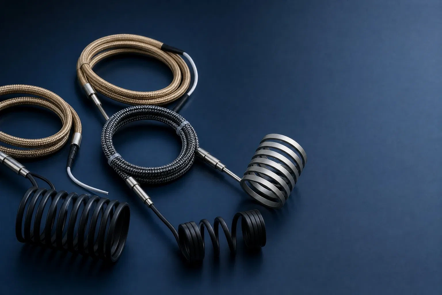
Hot Runner heaters for hot runner systems come mainly in two configurations, each with its own field of application:
| Configuration | How it’s installed | Minimum internal coil diameter | Typical application |
| Coiled | Wound helically around the nozzle body, pressed directly on or cast into a brass sleeve | Down to 7 mm | Individual nozzles in multi-cavity molds |
| Straight | Inserted into a channel machined directly into the metal block | N/A | Manifolds and distribution blocks |
One feature that sets many modern mini-tubular heaters apart is a built-in thermocouple — typically type J — within the element body itself. This removes the need to drill and install a separate temperature sensor at every nozzle, which matters a lot in 16-, 32-cavity or larger molds, where each gate needs its own control loop. The integrated thermocouple also works as a backup: if the external sensor fails, the operator can keep monitoring that specific zone’s temperature without disassembling the nozzle.
Why miniaturization is the real engineering challenge
The push toward smaller and smaller heaters isn’t cosmetic; it tracks a real trend in injection molding toward higher-cavitation molds and lighter parts — medical micro-molding, electronic components, connectors — where dozens of cavities need to fit into a limited mold space. Once nozzle spacing drops to 7 mm, 5.8 mm, or even 4.5 mm, there’s simply no physical margin left for a conventionally-sized tubular heater; the design of the whole system depends on a heater that can deliver enough power density within a minimal cross-section.
That creates a real engineering tension that every mini-tubular heater manufacturer has to solve: shrinking the diameter also shrinks the surface area available to dissipate the heat generated by the resistive wire, which forces adjustments to wire resistivity, MgO compaction, and tube wall thickness to prevent premature degradation from internal overheating. The most advanced products on the market have reached cross-sections as small as 1.0 x 1.6 mm without sacrificing dielectric strength or expected service life, which says a lot about how far metallurgy and compaction processes in this product category have advanced in recent years.
Sheath materials and their relationship to operating temperature
| Sheath material | Continuous operating temperature | Thermal fatigue resistance | Oxidation resistance | Recommended use |
| Stainless steel (304/316) | Up to ~650-800 °C | Good under moderate cycling | Good | PP, PE, PS, ABS and commodity thermoplastics |
| Inconel (600/601) | >800 °C sustained | High, even under aggressive cycling | Very high | PEEK, PPS, high-performance polyamides, demanding thermal cycles |
The choice of sheath metal is not a minor detail. Stainless steel sheaths are the standard option for continuous operating temperatures up to roughly 650-800 °C, covering the large majority of commodity thermoplastic molding applications. When the process involves high-melt engineering resins or when the thermal cycling is particularly aggressive, alloys such as Inconel are used instead, offering better resistance to thermal fatigue and oxidation at higher sustained temperatures. Choosing the wrong sheath material is one of the most common causes of premature mini-tubular heater failure: a standard stainless steel tube continuously subjected to thermal cycles above its design range develops fatigue and micro-cracks that eventually let moisture into the MgO, compromising the electrical insulation.
Wide common-specifications table
| Parameter | Typical range | Notes |
| Cross-section | 1.3 – 4.3 mm | Circular, oval, or rectangular by model |
| Wall thickness (oval/rectangular section) | 1.4 – 2.3 mm | High-density flat profiles |
| Minimum internal coiling diameter | 7 mm | Coiled configuration |
| Minimum supported nozzle spacing | 4.5 – 7 mm | Depends on hot runner system design |
| Sheath material | Stainless steel / Inconel | See materials table above |
| Resistive wire | Ni-Cr 80/20 | Insulated in compacted MgO |
| Sheath temperature | Up to 650-800 °C (SS) / >800 °C (Inconel) | Continuous |
| Integrated thermocouple | Type J (optional/common) | Reduces need for external sensor |
| Dielectric strength (no TC, straight) | ~1,250 V | Lower with integrated thermocouple |
| Maximum allowable leakage current | < 0.5 mA | Per installation standard |
| Minimum cold-end length | ~50 mm | Needed to avoid terminal overheating |
| Typical power (500 mm heated length) | 200 – 300 W at 230 V | Varies by section and application |
| Maximum allowable current | Up to 4 A | Depends on section and material |
Selection criteria for a hot runner system
Choosing the right mini-tubular heater for a hot runner project requires looking beyond rated power. Physical nozzle spacing determines from the outset which coil diameter is viable; the heated length and the cold-end length must match the exact geometry of each nozzle, since there is rarely a universal standard shared across hot runner system manufacturers. The element’s dielectric strength must meet the installation’s electrical safety requirements, especially in environments where allowable leakage current is limited to fractions of a milliamp. Finally, geometric compatibility with the mounting system — a steel clamping band, a cast brass sleeve, or direct insertion — shapes both the assembly process and the efficiency of heat transfer to the nozzle body, since poor thermal contact between the element and the surrounding metal creates cold spots that translate directly into filling defects in the molded part.
Applications beyond standard injection molding
While the dominant use of mini-tubular heaters is heating hot runner nozzles and manifolds in plastic injection molding, their compact profile and fast thermal response make them just as valuable in packaging machinery that needs heat-sealing in tight spaces, in micro-molding equipment for medical and electronic components where part weight can be a fraction of a gram, and in retrofit projects for specialized tooling where a conventional tubular heater simply doesn’t fit the available space in the original mold.
Application case: multi-cavity mold for electronic components
An electronic connector manufacturer running a 32-cavity mold to produce sub-1-gram precision components faced a recurring problem of flow lines and flash on the parts farthest from the central injection point. Diagnosis revealed that the original hot runner system used standard-section heaters with only 6 mm of nozzle spacing, which had forced poor thermal contact installations at several positions just to physically fit the elements. Migrating to reduced-section mini-tubular heaters with an integrated type J thermocouple let every nozzle house its own element with uniform contact along the full heated length, enabling individual zone temperature control instead of grouped zones. The result was a measurable drop in rejects from incomplete filling and greater part-weight consistency across all 32 cavities.
Frequently asked questions
What’s the real difference between “mini-tubular” and “micro-tubular”? In industry practice, both terms are used interchangeably to describe reduced-section tubular heaters designed for hot runner use; some manufacturers reserve “micro-tubular” for the most extreme sections, below 2 mm, but there is no universal standard formally separating the two categories.
Can these heaters be repaired or rewound? It’s not a recommended practice. Given the level of MgO compaction and the winding precision required to achieve uniform contact on the nozzle, a field repair attempt almost always results in irregular power density and hot spots that push the repaired element’s service life well below that of a new part.
What’s the typical service life of a properly selected mini-tubular heater? It depends heavily on the thermal cycling regime and on whether the sheath material was correctly matched to the process temperature, but under operating conditions within the design range, several years of continuous service before normal thermal fatigue justifies preventive replacement is a reasonable expectation.
Does the integrated thermocouple fully replace the mold control system’s temperature sensor? In most installations, yes, since the integrated thermocouple measures directly at the heating point and eliminates the thermal lag of a sensor installed in a separate position; some redundant control systems, however, keep an additional independent sensor at the manifold as a safety backup, especially in high-value molds where an undetected control-loop failure would be costly.