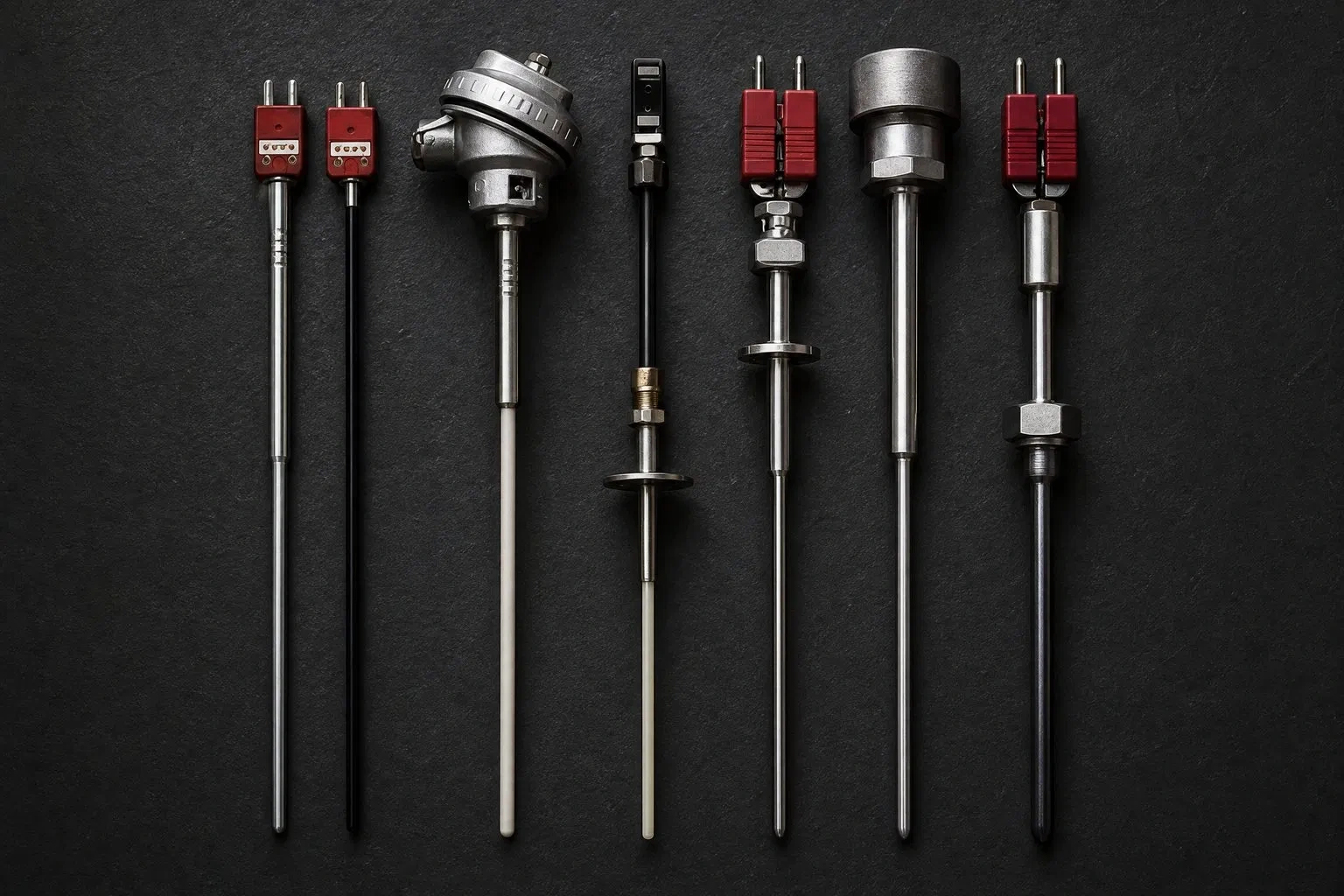
When a temperature reading starts drifting or acting up on an industrial line, the first instinct is almost always to swap the thermocouple. It’s the cheapest, most visible component, and the easiest one to blame. In practice, though, a large share of “sensor failures” have nothing to do with the thermocouple wire itself — they trace back to the accessories around it: the connector joining it to the control loop, the well protecting it from the process, the block insulating its terminals, or the head sealing its connection.
Diagnosing by accessory instead of replacing by reflex saves downtime and stops the same failure from resurfacing weeks later with a brand-new sensor. This guide walks through the six most common causes of industrial temperature measurement failure and the specific accessory engineered to fix each one.
Quick diagnostic table
| Symptom on the floor | Likely root cause | Accessory that fixes it |
| Reading jumps or fluctuates for no clear reason | Parasitic junction from a mismatched connector alloy | Plugs and Connectors for Type J and K Thermocouples |
| Sensor degrades or breaks within weeks | Direct process attack: pressure, abrasion, chemical agents | Thermowells (Temperature Sensor Pockets) |
| Slow, steady drift in hydrogen or vacuum atmospheres | Contamination migrating from an inadequate protection material | Ceramic Protection Tube for Thermocouple |
| Catastrophic failure in molten metal or slag above 1600 °C | Protection material insufficient for the environment | Silicon Nitride Thermocouple Protection Tubes |
| Intermittent short circuits or signal noise | Insufficient insulation at the internal junction point | Terminal Block — Ceramic Block for Temperature Sensors |
| Corrosion or moisture failure at the connection box | Unsealed head or unsuitable head material | Connection Heads for RTD and Thermocouples |
The standards framework before you diagnose
Before getting into each accessory, it helps to know what governs thermocouple tolerance and identification — a lot of “accessory errors” are really mixed-standard errors:
| Standard | What it governs | Key figure |
| IEC 60584-1 | EMF tolerance by type and class | Class 1: ±1.5 °C or ±0.004×|t| (whichever is greater); Class 2: ±2.5 °C or ±0.0075×|t| |
| ASTM E230 / ANSI MC96.1 | US tolerance classes and color coding | Type K positive lead is yellow; under IEC 60584-3 it’s green |
| DIN 43710 | Legacy German standard for Type J and K | Still found in older European equipment, with different color codes |
| IEC 60584-3 | International color-coding standard | Outer sheath by type: K=green, J=black, T=brown, N=pink |
Mixing an ANSI-built thermocouple with an IEC-labeled connector or extension cable is a silent error source: the colors don’t match, and a technician relying on color alone can reverse polarity without realizing it.
1. Erratic readings: it’s almost always the connector
When a reading fluctuates with nothing else on the process having changed, the first suspect shouldn’t be the sensor — it should be the junction where the thermocouple meets the extension cable or the instrument. Thermocouple connectors aren’t generic electrical terminals: they’re manufactured with the same compensated alloys as the corresponding thermocouple. Using a connector of a different metal creates an extra parasitic junction that adds or subtracts real millivolts from the signal, producing a false reading no software calibration can fix.
Alloys by thermocouple type (a quick reference so the connector always matches the sensor):
| Type | Positive leg | Negative leg | Typical range |
| K | Chromel (NiCr) | Alumel (NiAl) | -200 to 1260 °C |
| J | Iron | Constantan (CuNi) | -40 to 750 °C |
| T | Copper | Constantan (CuNi) | -200 to 350 °C |
| N | Nicrosil | Nisil | -200 to 1300 °C |
| E | Chromel | Constantan | -200 to 900 °C |
| R / S | Platinum-Rhodium | Platinum | 0 to 1480 °C |
Connectors come in two standardized sizes (miniature and standard, per IEC 60584-3) and two body types: thermoplastic (rated to 200 °C continuous, general use) and ceramic (up to 650 °C, for heads exposed to higher ambient temperature). Specifying the wrong size is a common cause of loose connections that create variable contact resistance.
2. Sensor breaks within weeks: missing mechanical protection
A bare thermocouple exposed directly to an aggressive process — pressure, vibration, particle abrasion, chemical attack — has a short service life regardless of wire quality. Thermowells act as a physical barrier between the sensor and the process, manufactured in stainless steel or exotic alloys depending on the corrosion profile expected.
Thermowell selection is more than a material question. Three engineering variables determine whether one lasts or fails by fatigue:
- Immersion length: must be long enough to keep the sensing tip out of the thermal boundary layer at the pipe wall; too shallow an immersion introduces error from heat conduction along the well itself.
- Wake (vortex-shedding) frequency: in high-velocity fluids, a thermowell can resonate with the vortices its own presence sheds into the flow, causing fatigue failure — the industry reference calculation is ASME PTC 19.3 TW.
- Tip wall thickness: higher process pressure and velocity call for greater thickness; straight, stepped, or tapered thermowells are chosen based on this tradeoff between mechanical strength and thermal response time.
Available in threaded, flanged, or weld-in configurations, they also let you pull and replace the sensor without shutting down or depressurizing the line. For chloride- or acid-bearing environments, alloys like Inconel 600/625 or Hastelloy far outperform 316 stainless steel against pitting corrosion.
3. Slow drift in hydrogen, vacuum, or high-purity atmospheres
This is one of the least-diagnosed failure modes because it isn’t catastrophic — the sensor keeps working, but the reading drifts gradually. The usual cause is contaminant migration (silicon, carbon) from a standard-grade ceramic protection into the thermocouple metal in reducing or high-purity atmospheres.
Not all technical ceramics behave the same way against this:
| Material | Purity / composition | Max continuous temperature | Thermal shock resistance |
| High-purity alumina | ≥99.7% Al₂O₃ | ~1750-1800 °C | Moderate |
| Mullite | 3Al₂O₃·2SiO₂ | ~1700 °C | Good |
| Recrystallized alumina | ≥99.5% Al₂O₃, low porosity | ~1800 °C | Moderate-high |
A lower-purity alumina has more open porosity, which increases both gas permeability (critical under vacuum) and silica migration toward the sensor. Heatecx’s ceramic protection tube for thermocouple is manufactured with low-porosity precision ceramic technology specifically to minimize this migration, extending sensor life and keeping the reading reliable in high-temperature processes.
4. Catastrophic failure against molten metal or corrosive slag
When the environment exceeds what conventional alumina ceramic can handle — immersion in molten metal, aggressive slag, corrosive gases above 1600 °C — the fix is a higher-performance technical material. Silicon nitride (Si₃N₄) thermocouple protection tubes stand apart from conventional alumina in three critical properties:
| Property | Alumina (Al₂O₃) | Silicon nitride (Si₃N₄) |
| Flexural strength | ~300 MPa | ~700-900 MPa |
| Thermal shock resistance (allowable ΔT) | Low-moderate | High |
| Behavior in molten metal/slag | Corrodes/erodes | Stable, non-wetting to most molten metals |
| Continuous use temperature | ~1750 °C | ~1400-1650 °C depending on grade |
Silicon nitride’s microcrystalline structure gives it far greater mechanical strength — important in applications where the tube takes impact loading or repeated thermal shock from immersion and withdrawal — at the cost of a somewhat lower continuous-temperature ceiling than pure alumina. The choice between the two comes down to whether the dominant risk is chemical/mechanical (silicon nitride) or purely thermal at sustained extreme temperature (alumina).
5. Intermittent short circuits or electrical noise
If the signal shows noise or short circuits that come and go — especially after vibration or thermal cycling — check the terminal block inside the connection head. The terminal block (ceramic block) for temperature sensors is the junction point where millivolt (thermocouple) or resistance (RTD) signals pass to the monitoring system.
Block material isn’t cosmetic:
| Material | Dielectric strength | Max service temperature | Notes |
| Bakelite | Good at ambient temperature | ~120-150 °C | Economical, general use in cooler heads |
| Technical ceramic | Very high, stable with temperature | >500 °C depending on grade | Mandatory when the head sits near hot zones |
In RTD measurements, where the circuit’s own resistance is part of the measurement, a block with elevated contact resistance from corrosion or a loose fit introduces a systematic error that’s hard to catch without comparing against a reference — unlike a thermocouple, where a bad junction usually produces a more obviously erratic signal.
6. Corrosion or moisture at the connection box
Finally, if the failure is concentrated at the connection point — visible corrosion, moisture, oxidized terminals — the responsible component is the head. Connection heads for RTD and thermocouples shield electrical connections from mechanical damage, dust, and moisture, and are available in stainless steel, bakelite, or aluminum alloy.
Protection level is normally specified by IP rating:
| IP rating | Protection | Typical application |
| IP54 | Limited dust, splashing water | Indoors, controlled environments |
| IP65 | Total dust ingress protection, water jets | Outdoors, general process plants |
| IP66/IP67 | Total dust protection, temporary immersion or high-pressure jets | Pressure washdown, coastal outdoor, humid zones |
Heads come in two standardized forms (Form B and Form C per DIN 43729), which differ in internal chamber size and terminal block layout — relevant when replacing an existing head without redoing the wiring.
Quick selection guide by process condition
| Process condition | Recommended accessory |
| High pressure or need to pull the sensor without a shutdown | Threaded or flanged thermowell, wall thickness sized per ASME PTC 19.3 |
| Hydrogen, vacuum, or high-purity atmosphere | Low-porosity ceramic tube (≥99.7% alumina) |
| Molten metal or slag contact, above 1600 °C | Silicon nitride protection tube |
| Humid, dusty, or pressure-washed environment | IP66/IP67 connection head |
| Installations with frequent sensor changes | Compensated Type J/K connectors, standard or miniature |
| Electrical noise, signal interference, or RTD measurement | Ceramic terminal block |
Application case: heat treatment furnace
A heat treatment plant was replacing thermocouples every 3–4 weeks in an annealing furnace, assuming normal sensor wear. Diagnosing by accessory revealed two simultaneous causes: the installed connectors were generic, non-compensated alloy, creating a parasitic junction that distorted the PID controller’s reading; and the thermocouple was exposed directly to the furnace environment with no protective well. After switching to flanged thermowells and correctly-alloyed Type K connectors, sensor life extended from weeks to over a year, and reading stability eliminated recurring manual PID adjustments.
Second case: non-ferrous metal foundry
At an aluminum foundry, thermocouples immersed directly in the crucible were failing within days from chemical attack by the molten metal on standard alumina ceramic. Switching to silicon nitride protection tubes, with their higher resistance to wetting by molten metal and to the thermal shock of repeated immersion, extended service life from days to several weeks of continuous operation, cutting both replacement cost and the risk of unplanned downtime from lost readings during pours.
Preventive maintenance by accessory
A basic inspection program catches failures before they happen:
- Connectors: check tightness and absence of oxidation at every scheduled shutdown; confirm polarity and type match the sensor.
- Thermowells: ultrasonic wall-thickness measurement at intervals set by process corrosivity, especially on high-velocity lines.
- Ceramic and silicon nitride tubes: visual inspection for cracks or chipping after each immersion/withdrawal cycle in batch processes.
- Terminal blocks: cleaning and contact-resistance checks on RTD measurements, where the error is less obvious on visual inspection.
- Heads: inspect the sealing gasket and actual IP rating after exposure to pressure washdown or cleaning chemicals.
Why Choose Heatecx
Heatecx manufactures machinery and raw materials for electric heating elements and industrial heating systems directly from its facility in Shenzhen, China, with vertical integration between machinery and raw material production. That means direct engineering support to specify the right accessory for your process, plus 100% batch testing before shipment — no intermediaries diluting technical traceability.
Browse the full range of Heatecx temperature sensor accessories to specify the exact component your process needs.